Fracture Mechanics Brittle fracture
Fracture Mechanics Brittle fracture. Fracture mechanics is used to formulate quantitatively The degree of Safety of a structure against brittle fracture The conditions necessary for crack initiation, propagation and arrest


Fracture Mechanics Brittle fracture
E N D
Presentation Transcript
Fracture Mechanics Brittle fracture • Fracture mechanics is used to formulate quantitatively • The degree of Safety of a structure against brittle fracture • The conditions necessary for crack initiation, propagation and arrest • The residual life in a component subjected to dynamic/fatigue loading
Fracture mechanics identifies three primary factors that control the susceptibility • of a structure to brittle failure. • Material Fracture Toughness. Material fracture toughness may be defined as the ability to carry loads or deform plastically in the presence of a notch. It may be described in terms of the critical stress intensity factor, KIc, under a variety of conditions. (These terms and conditions are fully discussed in the following chapters.) • 2. Crack Size. Fractures initiate from discontinuities that can vary from • extremely small cracks to much larger weld or fatigue cracks. Furthermore, • although good fabrication practice and inspection can minimize the size and • number of cracks, most complex mechanical components cannot be fabricated without discontinuities of one type or another. • 3. Stress Level. For the most part, tensile stresses are necessary for brittle • fracture to occur. These stresses are determined by a stress analysis of the • particular component. • Other factors such as temperature, loading rate, stress concentrations, • residual stresses, etc., influence these three primary factors.
Fracture at the Atomic level • Two atoms or a set of atoms are bonded together by cohesive energy or bond energy. • Two atoms (or sets of atoms) are said to be fractured if the bonds between the two atoms (or sets of atoms) are broken by externally applied tensile load Theoretical Cohesive Stress If a tensile force ‘T’ is applied to separate the two atoms, then bond or cohesive energy is (2.1) Where is the equilibrium spacing between two atoms. Idealizing force-displacement relation as one half of sine wave (2.2)
Theoretical Cohesive Stress (Contd.) Assuming that the origin is defined at and for small displacement relationship is assumed to be linear such that Hence force-displacement relationship is given by (2.2) Bond stiffness ‘k’ is given by (2.3) If there are n bonds acing per unit area and assuming as gage length and multiplying eq. 2.3 by n then ‘k’ becomes young’s modulus and beecomes cohesive stress such that (2.4) Or (2.5) If is assumed to be approximately equal to the atomic spacing
Theoretical Cohesive Stress (Contd.) The surface energy can be estimated as (2.6) The surface energy per unit area is equal to one half the fracture energy because two surfaces are created when a material fractures. Using eq. 2.4 in to eq.2.6 (2.7)
Fracture stress for realistic material Inglis (1913) analyzed for the flat plate with an elliptical hole with major axis 2a and minor axis 2b, subjected to far end stress The stress at the tip of the major axis (point A) is given by (2.8) The ratio is defined as the stress concentration factor, When a = b, it is a circular hole, then When b is very very small, Inglis define radius of curvature as (2.9) And the tip stress as (2.10)
Fracture stress for realistic material (contd.) When a >> b eq. 2.10 becomes (2.11) For a sharp crack, a >>> b, and stress at the crack tip tends to Assuming that for a metal, plastic deformation is zero and the sharpest crack may have root radius as atomic spacing then the stress is given by (2.12) When far end stress reaches fracture stress , crack propagates and the stress at A reaches cohesive stress then using eq. 2.7 (2.13) This would
Griffith’s Energy balance approach • First documented paper on fracture (1920) • Considered as father of Fracture Mechanics
Griffith’s Energy balance approach (Contd.) A A Griffith laid the foundations of modern fracture mechanics by designing a criterion for fast fracture. He assumed that pre-existing flaws propagate under the influence of an applied stress only if the total energy of the system is thereby reduced. Thus, Griffith's theory is not concerned with crack tip processes or the micromechanisms by which a crack advances. Griffith proposed that ‘There is a simple energy balance consisting of the decrease in potential energy with in the stressed body due to crack extension and this decrease is balanced by increase in surface energy due to increased crack surface’ Griffith theory establishes theoretical strength of brittle material and relationship between fracture strength and flaw size ‘a’
Griffith’s Energy balance approach (Contd.) The initial strain energy for the uncracked plate per thickness is (2.14) On creating a crack of size 2a, the tensile force on an element ds on elliptic hole is relaxed from to zero. The elastic strain energy released per unit width due to introduction of a crack of length 2a is given by (2.15)
Griffith’s Energy balance approach (Contd.) External work = (2.16) The potential or internal energy of the body is Due to creation of new surface increase in surface energy is (2.17) The total elastic energy of the cracked plate is (2.18)
Griffith’s Energy balance approach (Contd.) The variation of with crack extension should be minimum Denoting as during fracture (2.19) for plane stress (2.20) for plane strain The Griffith theory is obeyed by materials which fail in a completely brittle elastic manner, e.g. glass, mica, diamond and refractory metals.
Griffith’s Energy balance approach (Contd.) Griffith extrapolated surface tension values of soda lime glass from high temperature to obtain the value at room temperature as Using value of E = 62GPa,The value of as 0.15 From the experimental study on spherical vessels he calculated as 0.25 – 0.28 However, it is important to note that according to the Griffith theory, it is impossible to initiate brittle fracture unless pre-existing defects are present, so that fracture is always considered to be propagation- (rather than nucleation-) controlled; this is a serious short-coming of the theory.
Modification for Ductile Materials For more ductile materials (e.g. metals and plastics) it is found that the functional form of the Griffith relationship is still obeyed, i.e. . However, the proportionality constant can be used to evaluate gs (provided E is known) and if this is done, one finds the value is many orders of magnitude higher than what is known to be the true value of the surface energy (which can be determined by other means). For these materials plastic deformation accompanies crack propagation even though fracture is macroscopically brittle; The released strain energy is then largely dissipated by producing localized plastic flow at the crack tip. Irwin and Orowan modified the Griffith theory and came out with an expression Where gprepresents energy expended in plastic work. Typically for cleavage in metallic materials gp=104 J/m2 and gs=1 J/m2. Since gp>> gs we have
Strain Energy Release Rate The strain energy release rate usually referred to Note that the strain energy release rate is respect to crack length and most definitely not time. Fracture occurs when reaches a critical value which is denoted . At fracture we have so that One disadvantage of using is that in order to determine it is necessary to know E as well as . This can be a problem with some materials, eg polymers and composites, where varies with composition and processing. In practice, it is usually more convenient to combine E and in a single fracture toughness parameter where . Then can be simply determined experimentally using procedures which are well established.
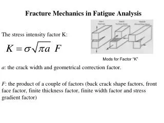
LINEAR ELASTIC FRACTURE MECHANICS (LEFM)For LEFM the structure obeys Hooke’s law and global behavior is linear and if any local small scale crack tip plasticity is ignored The fundamental principle of fracture mechanics is that the stress field around a crack tip being characterized by stress intensity factor K which is related to both the stress and the size of the flaw. The analytic development of the stress intensity factor is described for a number of common specimen and crack geometries below. The three modes of fracture Mode I - Opening mode: where the crack surfaces separate symmetrically with respect to the plane occupied by the crack prior to the deformation (results from normal stresses perpendicular to the crack plane); Mode II - Sliding mode: where the crack surfaces glide over one another in opposite directions but in the same plane (results from in-plane shear); and Mode III - Tearing mode: where the crack surfaces are displaced in the crack plane and parallel to the crack front (results from out-of-plane shear).
LINEAR ELASTIC FRACTURE MECHANICS (Contd.) In the 1950s Irwin [7] and coworkers introduced the concept of stress intensity factor, which defines the stress field around the crack tip, taking into account crack length, applied stress s and shape factor Y( which accounts for finite size of the component and local geometric features). The Airy stress function. In stress analysis each point, x,y,z, of a stressed solid undergoes the stresses; sxsy, sz, txy, txz,tyz. With reference to figure 2.3, when a body is loaded and these loads are within the same plane, say the x-y plane, two different loading conditions are possible: 1. plane stress (PSS), when the thickness of the body is comparable to the size of the plastic zone and a free contraction of lateral surfaces occurs, and, 2. plane strain (PSN), when the specimen is thick enough to avoid contraction in the thickness z-direction.
In the former case, the overall stress state is reduced to the three components; sx, sy, txy, since; sz, txz, tyz= 0, while, in the latter case, a normal stress, sz, is induced which prevents the z displacement, ez = w = 0. Hence, from Hooke's law: sz = ν (sx+sy) where νis Poisson's ratio. For plane problems, the equilibrium conditions are: If is the Airy’s stress function satisfying the biharmonic compatibility Conditions
And are 2nd and 1st integrals of Z(z) Then the stresses are given by Then For problems with crack tip Westergaard introduced Airy’s stress function as Where Z is an analytic complex function
Opening mode analysis or Mode I • Boundary Conditions : • At infinity • On crack faces Consider an infinite plate a crack of length 2a subjected to a biaxial State of stress. Defining: By replacing z by z+a , origin shifted to crack tip.
And when |z|0 at the vicinity of the crack tip KI must be real and a constant at the crack tip. This is due to a Singularity given by The parameter KI is called the stress intensity factor for opening mode I. Since origin is shifted to crack tip, it is easier to use polar Coordinates, Using Further Simplification gives:
The vertical displacements at any position along x-axis (q = 0) is given by The strain energy required for creation of crack is given by the work done by force acting on the crack face while relaxing the stress s to zero
Sliding mode analysis or Mode 2 For problems with crack tip under shear loading, Airy’s stress function is taken as Using Air’s definition for stresses Using a Westergaard stress function of the form
Boundary Conditions : • At infinity • On crack faces With usual simplification would give the stresses as Displacement components are given by
Tearing mode analysis or Mode 3 In this case the crack is displaced along z-axis. Here the displacements u and v are set to zero and hence