Download
1 / 19
590 likes | 1.68k Vues
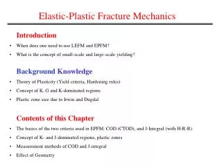
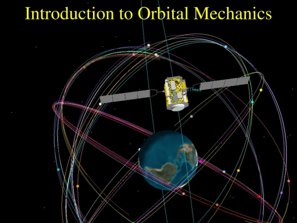
Introduction to FRACTURE MECHANICS. σ. t. Elasticity versus fracture. This fundamental design formula is valid: Below load bearing capacity Within elastic region. ekspl =R m /s < R H. but it turned out to be unsatisfactory in two situations:.

E N D
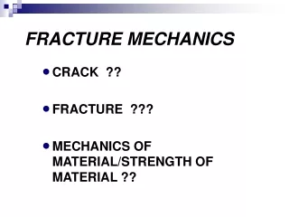
σ t Elasticity versus fracture This fundamental design formula is valid: • Below load bearing capacity • Within elastic region ekspl =Rm/s < RH but it turned out to be unsatisfactory in two situations: When loading (and consequently – stress) is varying in time: q=q(t) , P=P(t) Because of material FATIGUE (Fatigue Mechanics) When geometry of a structure yields stress concentration Beacuse of material CRACKING (Fracture Mechanics)
s so Lennart-Jones model Fr Fa Fa Fr m > n (m10, n 5) Reactive force (repulsion) Active force (attraction) For s=so Fr Fa Fa Fr
s > so F F 0 0 s Lennart-Jones model F Fr Fa Fa Fr F =s-so so
F 0 Lennart-Jones model F=FR =R =R
Lennart-Jones model m=10, n =5 =(101000)(FR experimental ) Reasons for discrepancy: • Extremely simplified two-atomic model • Defects of crystalline structure (theory of dislocation)
Fatigue Observed since prehistoric times: example – technology development in shipbuilding X century XV century XIX century
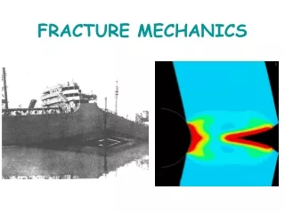
Fatigue A ship is working alternatively as double cantilever and simply supported beam Deck under tension! Keel under compression! Until the middle of XX century the problem of ship cracking caused by fatigue remained unsolved. Keel under tension! Deck under compression!
Transporter SS Schenctady, cracked in half when docked in the port on 16.01.1943, Portland, OR
Fatigue Fatigue appearance accelerated when steam railways were introduced in XIX century. „The Rocket”, steam locomotive built byR. Stephenson, 1829
t Wheel axis cross-section A M A A A
Fatigue limit Fatigue A.Wöhler (1819-1914) Wöhler diagram for high-cycle fatigue Wöhler stand for fatigue investigation
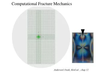
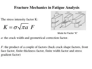
Stress approach Cracking q[Pa] G.Kirsch, 1898 – band of infinite width with circular hole σy= 3q y x q[Pa]
b a Cracking Stress approach q[Pa] q[Pa] C.E.Inglis, 1913 – A band of infinite width with elliptic hole y x σ 3q a b Independent of the hole half- radius size a !!! σ b 0
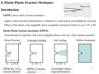
0 r x a Cracking H.M.Westergaard, 1939, N.I.Muskhelischvili, 1943 – analysed 2D stress field at the tip of a sharp slit A y For For Singularity! Stress intenstiy factor
Cracking Stress intensity factors were calculated for different configuration of loading and specimen geometry (G.Sih) Three typical cases (modes) can be distinguished: KII KI KIII Mode I - Tearing; crack surfaces separate perpendicularly to the crack front. Mode II – In-plane shear; crack surfaces slide perpendicularly to the crack front Mode III – Out-of-plane shear; crack surfaces slide parallely to the crack front .
Cracking Design criteria are: KI < KIc KII < KIIc KIII < KIIIc KIc , KIIc , KIIIc where are critical values of corresponding stress factors, being determined experimentally.
q c c 2l q Simple example of Fracture Mechanics application What is the length of a central slit we can introduce to the structure shown without the reduction of its load bearing capacity? (no interaction assumed) 2l≤2c or 2l2c ? For side crack For central crack If e.g. c = 2 cm 2l 5 cm