FRACTURE MECHANICS
FRACTURE MECHANICS. Silver Bridge.

FRACTURE MECHANICS
E N D
Presentation Transcript
Silver Bridge The Silver Bridge, named because of its shiny aluminum paint, was considered an engineering marvel at the time of its construction because the suspension component of the bridge was formed by eyelets at each end. The joints were similar to the link mechanism of a bicycle chain, an unfortunate design because this meant that if even one joint failed the whole bridge would fail. In 1967, this is exactly what happened and the bridge collapsed, in the end 46 lost their lives. Investigators later concluded that a north side joint had a fracture which had become corroded over the years, and it gave way to the heavy stresses from the rush hour traffic. An eyewitness later reported that she had heard a crackling noise and spotted metal debris on the roadway just 30 minutes before the collapse, indicating that there were apparent signs of failure.
Hyatt Regency The collapse on July 17, 1981, killed 114 people and injured more than 200 others, the deadliest structural failure in the USA history. It was caused by the failure of steel connections supporting the concrete and glass walkways, and provided a catalyst for changes in construction practices nationwide. Ultimate blame was pinned on the two structural engineers who designed the skywalks. One of them later testified that he never checked the skywalks' connections, and that he thought it was the responsibility of the fabricators to make sure the connections would hold.
Conventional Failure Analysis The most straightforward design consideration to avoid structural failure is obviously keep the maximum stress well under the posted material strength: Maximum Stress Strength of Material This maximum stress approach, although usually adequate when one principal stress dominates, may not be valid when the structure undergoes general multi-axial loadings. To address this issue, many failure criteria were proposed. Most of them are based on principal stresses, strains, or strain energy. By overlaying an "effective" strength of material and the loading conditions, one can determine the effectiveness of the structural elements. Applied StressFailure Criterion Still, in reality, many more factors are to be considered. For example, the material is never flawless; the assembly may not be perfect; the loading may not be as designed; the environment may be harsh; the maintenance may be poor; and the service life may have to be very long. Traditionally these concerns were (hopefully) offset by a single safety factor; that engineers employ like a second nature. Unfortunately, history showed that many structures failed way below their designed capacity.
Perhaps one of the most important questions in the design process would be: What Constitutes Mechanical Failure? In general, the various failure mechanisms may be classified into the two broad fields of Deformation and Fracture. A more detailed list would be: Excessive Elastic Deformation Unstable Elastic Deformation (Buckling) Plastic Deformation Fracture Fatigue Creep Stress Corrosion Cracking The occurrence of each failure mode depends on various factors
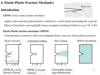
Evolution of Structural Design The art of structural design has drastically evolved through the history of mankind. A rather broad, but somehow specific, classification would be: I. Design Based on Previous successful designs II. Introduction of the Stress and Strain Concepts III. Strength of Materials Approach IV. Theory of Elasticity Approach V. Fracture Mechanics Approach Design Philosophies: For many applications, it’s sufficient to determine the maximum static or dynamic stress that the material can withstand, and then design the structure to ensure that the stresses remain below acceptable limits. More critical applications require some kind of defect tolerance analysis. In these cases, the material or structure is considered to contain flaws, and we must decide whether to replace the part; or leave it in service under a more tolerable loading for a certain period of time. This kind of decision is usually made using the disciplines of Fracture Mechanics.
Safe Life: The component is considered to be free of defects after fabrication and is designed to remain defect-free during service and withstand the maximum static or dynamic working stresses for a certain period of time. If flaws, cracks, or similar damages are visited during service the component should be discarded immediately. Fail Safe: The component is designed to withstand the maximum static or dynamic working stresses for a certain period of time in such a way that its probable failure would not be catastrophic. For example a pressure vessel designed to work under the leak-before-burst (LBB) condition should show leakage as a result of crack propagation. The aim is to prevent catastrophic failure by detecting the crack at its early stages of growth and also reducing the internal pressure. Damage Tolerance:The component is designed to withstand the maximum static or dynamic working stresses for a certain period of time even in presence of flaws, cracks, or similar damages of certain geometry and size.
Fracture Mechanics Fracture mechanics is a field of solid mechanics that deals with the mechanical behavior of cracked bodies.
From investigating fallen structures, engineers found that most failure began with cracks. These cracks may be caused by material defects (dislocation, impurities...), discontinuities in assembly and/or design (sharp corners, grooves, nicks, voids...), harsh environments (thermal stress, corrosion...) and damages in service (impact, fatigue, unexpected loads...). Most microscopic cracks are arrested inside the material but it takes one run-away crack to destroy the whole structure. To analyze the relationship among stresses, cracks, and fracture toughness, Fracture Mechanics was introduced. The first milestone was set by Griffith in his famous 1920 paper that quantitatively relates the flaw size to the fracture stresses. However, Griffith's approach is too primitive for engineering applications and is only good for brittle materials Applied stress Toughness Defect size
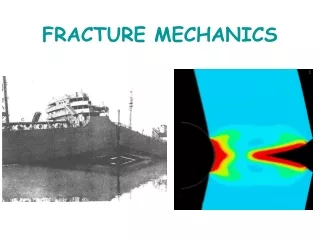
What is Fracture Mechanics and why do you care? Fracture Mechanics is all about figuring out how cracks think: where are they going to pop up next, are they going to grow or just hang out where they are? It is important to study how cracks behave because cracks can cause things to fail, something as small as a bone or as large as a ship. If a large structure, such as a building or a ship, cracks, this may lead to a catastrophic failure which could affect many people. The mechanics of fracture progressed from being a scientific curiosity to an engineering discipline, primarily because of what happened to the Liberty ships during World War II. The Liberty ships had an all-welded hull, as opposed to the riveted construction of traditional ship designs. Of the roughly 2700 liberty ships build during World War II, approximately 400 sustained fractures, of which 90 were considered serious. In 20 ships the failure was essentially total, and about half of these broke completely in two.
Mode I Mode III Mode II Fracture Modes Forces are simplified into three different "modes", basically three ways the forces can act and what kind of fracture they cause:
EARLY FOUNDATIONSOF STRENGTH OF MATERIAL The notes of Leonardo da Vinci (1452–1519) are the earliest records indicating a concept for evaluating the strength of materials. He suggested an experiment (da Vinci’s sketch shown in Fig. 1.2), which is believed, was intended to establish a “law” for the influence of length on the strength of all types of materials. Even though it is unknown if the experiments were performed at that time, this was an early indication of the size effects on the strength of material. A longer wire corresponds to a larger sample volume and provides a higher probability of sampling a region containing a flaw.
The science and early evolution of the strength of materials concepts can be attributed to Galileo. In the early 17th century, Galileo turned his attention to structural mechanics while he was under house arrest and was banned from celestial mechanics. In his book Due Nuove Scienze, which was published in 1638, Galileo introduced the concept of tensile strength in simple tension, which he referred to as “absolute resistance to fracture.” His observation that the strength of the bar is proportional to the cross-sectional area and is independent of the length produced early strength of material concepts. It is an interesting fact that even Galileo noted an indication of size effect while he was visiting the Venetian Arsenal. He noticed a greater attention used by workers in the construction of big ships than in small ships. At that time one of the master builders explained to him that the large ships were assumed to be more brittle than the smaller vessels.
Robert Hooke It was Robert Hooke (1635–1702) who broke away from the traditional thinking of his era and introduced the concept of the true theory of elasticity or springiness in 1678. Hooke tested wire strings of 20 to 40 ft in length by adding weight and measuring displacements. He made an important observation: that the wire always returned to its original length after several tests on the same wire. His far-reaching statement implied that when a mechanical force is applied to a solid object, change in shape (by extension or compression) must take place, and accordingly the solid produces a reaction. Essentially, Hooke arrived at the conclusion that all solids and objects can behave like springs. Hooke’s law advanced two very important principles: 1. Recovery from elastic deformation. 2. Linear relationship between applied load and elastic deformation. Although rather simplistic in mathematical terms, this principle has been a significant help to engineering practitioners for more than 300 years.
Thomas Young From the principles of Hooke’s law, all subsequent contributions were based on the theory of elasticity. In 1807, Thomas Young published the definition of modulus of elasticity, which is also known as Young’s modulus. Young related stress (s) and strain (e) by using the modulus of elasticity (E) with a very simple equation s = E e From this point on in structural mechanics, quantitative methods could be used to design structures without having to constantly resort to testing.
Who started all this fracture mechanics stuff? In 1913, a a professor of Naval Architecture C.E. Inglis looked at a thin plate of glass with an elliptical hole in the middle, in a new and different way. The plate was pulled at both ends perpendicular to the ellipse. He found that point A, at the end of the ellipse, was feeling the most pressure. He also found that as the ratio of a/b gets bigger (the ellipse gets longer and thinner) that the stress at A becomes greater and greater. He also found that pulling on the plate in a direction parallel to the ellipse does not produce a great stress at A. This leads to the fact that a load perpendicular, not parallel, to the crack will make it grow. Then he looked at other plates with not-quite-elliptical holes. He realized that it's not really the shape of the hole that matters in cracking. What matters is the length of the crack that is perpendicular to the load and what the radius of curvature at the ends of the hole is. The longer the hole (or crack), the higher the stress, and the smaller the radius of curvature, the higher the stress.
The maximum net section stress at point A is provided by where is the nominal (remote) stress. Note that if a = b (circle) then A = 3 . When defining the radius of curvature = b2=a the maximum local stress A attains the form: STRESS IN AN INFINITE PLATE WITH AN ELLIPTICAL HOLE -INGLIS- The above criterion suffers from the major drawback. In particular, if 0 then A . This is not realistic, because no material can withstand infinite stress.
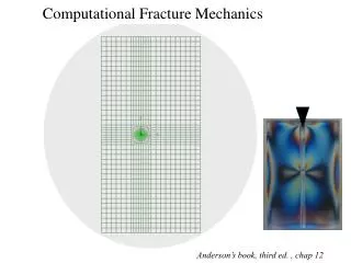
GENERAL NEAR-TIP FIELDS STRESS INTENSITY FACTORS-WESTERGAARD- It is possible to derive closed-form solutions for the stresses in the body, assuming linear elastic material behavior. The early works on this subject are due to Westergaard When defining a polar coordinate system (r;) with the origin at the crack tip the stress field in any linear elastic cracked body can be written as where k is a constant and fij is dimesionless function of . The stress near the crack tip varies with 1√r, regardless of the configuration of the cracked body. Note that when r 0 the stress approaches to ∞. In other words, when a body contains a crack, a strong concentration develops around a crack tip.
Westergaard For linear elastic material this stress concentration (Westergaard) has the same distribution close to the crack tip regardless of the size shape and specific boundary conditions of the body. Only the intensity of the stress concentration varies. For the same intensity, the stresses around the crack tip are identical. When = 0, the shear stress is zero and crack plane is a principal plane for pure Mode I loading. Then the stresses, in the close vicinity of the crack tip, assume the form The singularity dominated zone is defined as a region where this equation describes the crack tip stresses. Thus the stresses near the crack tip increase in proportion to K (K defines the amplitude of the crack tip singularity).Thus the stress intensity factor K completely defines the crack tip conditions (single parameters description of the crack tip conditions).
Energy Criterion - Griffith The paradox of a sharp crack motivated Griffith to develop a fracture theory based on energy rather than local stress. He observed that to introduce a crack into an elastically stressed body one would have to balance the decrease in potential energy (due to the release of stored elastic energy and the work done by external loads) and the increase in surface energy resulting from the presence of the crack which creates new surfaces. Recall, that surface energy arises from the non-equilibrium cofiguration of atoms at any surface of a solid. Likewise he reasoned that an existing crack would grow by some increment if the necessary surface energy was supplied to the system. According to the First law of thermodynamics, when a system goes from a nonequilibrium state to equilibrium, there will be a net decrease in energy. In 1920 Griffit happlied this idea to the formation of crack
Therefore, a crack can form (or an existing crack can grow) only if such a process causes the total energy to decrease or remain constant. Thus the critical condition for the fracture can be defined as the point at which crack growth occurs under equilibrium conditions. In mathematical terms the above statement reads: Griffith Criterion
Griffith Criterion Griffith wrote an expression for the change in total energy as a sum of the decrease in potential energy and the increase in surface energy Note that the Griffith criterion applies only to linear elastic material behavior. Thus the global behavior of the structure must be linear. Any nonlinear effects such as plasticity must be confined to a small region near the crack tip. Therefore: For the linear elastic solid with the plastic zone confined to a small region near the crack tip the fracture energy is constant. In many ductile materials, however, the fracture energy increases with with the crack growth. In such a case, the energy required for a unit advance of the crack is called the crack growth resistance R.
Plasticity effects in metals limited the theorem and it was not until Irwin’s work in 1948, that a modification was made to Griffith’s model to make it applicable to metals. Irwin’s first major contribution was to extend the Griffith approach to metals by including the energy dissipated by local plastic flow. Orowan independently proposed a similar modification to Griffith’s theory in 1949. Orowan limited practical use to brittle materials while Irwin made no such restrictions. It is an interesting fact and perhaps relevant to point out that the scientific curiosity towards fracture mechanics became a significantly important engineering discipline after the unfortunate failures of Liberty ships during World War II. The Liberty ships were built by the United States to support Britain’s war effort and used a new construction method for mass production in which the hull was welded instead of riveted. The Liberty ship program was an astounding success until 1943, when a Liberty ship broke completely in two while sailing in the North Pacific. Later, hundreds of other vessels sustained fractures. An investigation into Liberty ship failures pointed out poor toughness of steel and transition from ductile to brittle behavior at the service temperatures that ships experienced. It was noticed that the fractures initiated at the square hatched corners on the deck where there was a local stress concentration and the sharp corners acted like starter cracks.
Research into this problem was led by George Rankine Irwin at the Naval Research Laboratory in Washington, DC. It was the research during this period that resulted in the development and definition of what we now refer to as linear-elastic fracture mechanics (LEFM). A major breakthrough occurred in the early 1950s when Irwin and Kiesprovided the extension of Griffith theory for an arbitrary crack and proposed the criteria for the growth of this crack. The criterion was that the strain energy release rate (G) must be larger han the critical work (Gc), which is required to create a new unit crack area. Irwin also related strain energy release rate to the stress field at the crack tip using Westergaard’s work. Westergaard had developed a semi-inverse technique for analyzing stresses and displacements ahead of a crack tip. Using Westergaards’ method, Irwin showed that the stress field in the area of the crack tip is completely determined by a quantity K called the stress intensity factor.
Other serious failures that were experienced during that period were those of the de Havilland “Comet” commercial aircraft. The Comet was first manufactured in 1952, and was the first two-jet-engine aircraft to fly at 40,000 ft with a pressurized cabin. After about a year in service, three aircraft failed, resulting in the tragic loss of several lives. In 1955, Wells used fracture mechanics to show that the fuselage failures in several Comet jet aircraft resulted from fatigue cracks reaching a critical size. These cracks were initiated at windows and were caused by insufficient local reinforcement in combination with square corners, which produced higher stress concentrations. It was noticed that the fracture of welded Liberty ships, the pressurized cabin fractures of de Havilland Comet jet airplanes, bursts of several large petroleum storage tanks, and several other unpredicted failures, all seemed understandable in terms of the new fracture strength points of view. The evaluation method was straightforward, a value of Gc was established from laboratory tests on precracked specimens and the value of the driving force G that tended to extend the starting crack was computed using appropriate stress analysis methods.
The comparison showed that the fracture toughness had not been large enough to prevent crack propagation in the failure cases mentioned above. The use of the optical method “photoelasticity” to examine the stress fields around the tip of a running crack was published by Wells and Post in 1958 and Irwin observed that the photoelastic fringes not only formed closed loops at the crack tip as predicted by singular stress field equations but also showed a tilt as a result of the near specimen boundaries. In 1960, a significant contribution to the development of LEFM was put forth when Paris and his coworkers advanced an idea to apply fracture mechanics principles to fatigue crack growth. The work by Paris and colleagues was a landmark in the fatigue aspects of fracture mechanics, and yielded the equation
Linear elastic fracture mechanics is not valid when significant plastic deformation precedes failure. Although earlier theoretical developments were aimed at understanding brittle crack behavior, it became apparent from experiments that except for a few, most materials are ductile and therefore linear elastic analysis should be modified accordingly. Dugdale in 1960 and Barenbelt in 1962 made the first attempts to include cohesive forces in the crack tip region by developing an elaborate model within the limits of elasticity. Later, in 1968, Rice conducted a simplified analysis of complete plastic zone formation, approximated by a circular region ahead of the crack tip. The results derived from the energy–momentum tensor concept and applied to elastic cracks were extended to include plastic cracks by defining a path-independent integral termed the J integral. The plastic zone size and the crack opening displacement were found to correlate with the elastic stress intensity factor criterion. In 1976, Sih introduced the strain–energy density concept, which was a departure from classical fracture mechanics. He was able to characterize mixed-mode extension problems with this method, which also provided the direction of the crack propagation in addition to the amplitude of the stress field
ENERGY RELEASE RATE In 1956 Irwin proposed an energy approach equivalent to Griffith model but more suitable for solving engineering problems. He introduced an energy release rate G as a measure of the energy available for an increment of crack extension where B is the thickness of a plane structure and is the potential energy of an elastic body. Note that the term rate does not refer to a derivative with respect to time. G is the rate of change in potential energy with respect to crack area. G, as it follows from the derivative of a potential, is also called the crack extension force or the crack driving force.
Linear Elastic Fracture Mechanics -Energy Approach- Consider a deformable body in an equilibrium state under the influence of surface tractions and body forces. The virtual work can be defined as “the work done on a deformable body, by all the forces acting on it, as the body is given a small hypothetical displacement which is consistent with the constraints present”. The virtual displacements are represented by the symbol “δ” In general, the loadings consist of body forces and surface tractions. The later are prescribed over a part of the boundary designated byS Over the remaining boundary, designated by Su , the displacement field u is prescribed. However, it must be ensured that u = 0 on Su to avoid violating the constraints.
During the elastic deformation the external work is converted to stored elastic strain energy, and vice versa, so that the variation of the total potential energy is zero. In Fracture Mechanics, however, the total potential energy is the only source for crack growth. Accordingly, an energy criterion for the onset of crack growth can be defined in the following general form: in which G is called the energy release rate (also known as the crack driving force), A is the cracked area, and R is the resistance of the material to crack growth. The energy release rate, G, can be considered as the energy source for the crack growth and may be obtained from the stress analysis of the cracked geometry. On the other hand, the resistance to crack growth, R, can be considered as the energy sink and depends on the operating fracture mechanism.
Fixed Displacement Condition Suppose that we have stretched a cracked component by the amount Δ. The amount of elastic strain energy stored in the component is equal to the triangle ABD and the slope of the load-displacement curve represents the stiffness of the component. Let us initially assume that the stored energy is sufficient to maintain an incremental crack growth, a, under the fixed displacement condition. Since the component with a longer crack has a lower stiffness, the stored elastic energy decreases to a new level equal to the triangle ACD. Since there is no externally applied load in the system, the total potential energy is equal to the strain energy, the only source to provide the required energy for the crack growth. Hence, we may write: B is the thickness of the component
Constant Load Condition Consider a cracked component under a constant external load P The amount of elastic strain energy stored in the component is equal to the triangle ABE. Now we assume that the available energy is sufficient to maintain an incremental crack growth, da, under the constant load condition. The component with a longer crack has a lower stiffness but, in this case, the stored elastic energy increases to a new level equal to the triangle ACD. The reason is that an excess amount of energy provided by moving the constant load P through the distance dΔ, equal to rectangle BCDE, has now been added to the system. Hence, we may write:
Note that in both cases the energy release rate is provided by the stored energy U and is equal to: Moreover, for both cases we may write: in which C is the compliance of the component. The above equation can be used to obtain G provided that the variation of compliance with the crack length is available. In practice, various analytical, numerical, and experimental techniques are available for this purpose.
(**) Large plate under remote uniaxial tensile stress • The strain energy of the above system consists of two parts: • the elastic energy of the plate without crack • plus the strain energy required to introduce the crack. • The latter is equal in magnitude to the work required to close the crack by the stresses acting in its position. The expression for v can be obtained from a complete stress analysis of this cracked geometry. This expression would be: which shows that the crack-opening is maximum at the center and zero at the tip. Substituting for v (**):
which in combination with Eq.(°°)results in: (°°) The above equation was derived for two crack tips. Accordingly, the G expression for each crack tip would be: The above equation is remarkable as it shows how the energy release rate increases with increasing the far-field stress and the crack length. We may generalize the above equation for different components as: in which is a parameter that depends on the geometry and loading condition.
Critical Energy Release Rate -R- We may perform a fracture toughness test on the experimental specimen by gradually increasing the stress and noting the critical stress level σc at which the crack starts to grow. Accordingly, we may obtain the critical energy release rate as: which, in fact, represents a material property called fracture toughness.
INSTABILITY AND THE R-CURVE According to definition crack extension occurs when G = 2wf = R, where R is called the material resistance to crack extension. Depending on how G and R vary with the crack size the crack growth may be stable or unstable as shown in the figure below, which corresponds to a response of the Griffith crack. A plot of R versus crack extension is called a resistance or R curve. The corresponding plot of G versus crack extension is the driving force. Condition for the stable crack growth Condition for the unstable crack growth
When the resisting curve is flat, one can derine a critical value of energy release rate, Gf , unambiguously. A material with a rising R curve, however, cannot be uniquely characterized with a single toughness value. A flaw structure fails when the driving force curve is tangent with R curve, but this point of tangency depends on the shape of the driving force, which depends on configuration of the structure. The R curve for an ideally brittle material is flat because the surface energy is an invariant property. However, when nonlinear material behavior accompanies fracture, the R curve can take on a variety of shapes. Materials with rising R curves can be characterized by the value of G at initiation of crack growth. This value, however, characterizes only the onset of crack growth and provides no information on the shape of the R curve. Ideally, the R curve, should only be a property of the material and not depend on the size or shape of the crack body. Much of fracture mechanics assumes that the fracture toughness is material property.
The increase in resistance can be attributed to the formation of shear lips, which in turn results from plastic deformations at the crack tip. We will elaborate on this issue later when we discuss the crack tip plasticity. The criteria for unstable crack growth under constant load for plane stress can be defined as:
Crack Branching Another interesting aspect of a growing crack is branching. Under constant load, where the energy release rate increases with further crack growth, there might be a point where the available energy becomes twice the energy required to grow a single crack.This surplus of energy usually accelerates the crack, but if the material permits the situation may change in favor of crack branching. In general, when we observe that a component has been shattered into numerous pieces, we may think of too much energy available and/or too little energy required for crack to grow. The examples may include the fracture caused by an explosion and/or a glass of water slipping from your hand!
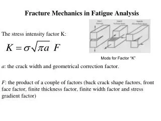
LEFM, Stress Approach The Mode I stress intensity factor K, is defined as: The following general expression can be considered for the stresses in a cracked body: It is clear that the first term is dominant very near to the crack tip. As we move further from the crack tip the singular term weakens and the additional terms become significant.
Design Philosophy Based on LEFM So far we have learned that cracks may start growing when the stress intensity factor (SIF) reaches a critical value Kc, called fracture toughness. Later we will show that the SIF can be related to the far-field stress and crack length by the following general expression: in which Y is a geometric factor. Thus for the design of a cracked, or potentially cracked, structure we have to decide what design variables can be selected, as only two of these variables can be fixed, and the third must be determined. For example we may select a special steel to resist a corrosive liquid, so KC is fixed, and the design stress level may also be fixed due to weight considerations. In this case we may calculate the maximum size of tolerable cracks