Download
1 / 14
150 likes | 411 Vues
Fracture Mechanics of One-Dimensional Nanostructures. Carbon Nanotube Source. Arc-grown Multi-wall Carbon Nanotubes (MWCNTs) from MER Corp. AZ. were studied in this work. A simple fractionation process was used to remove some impurities and increase nanotube concentration.

E N D
Carbon Nanotube Source Arc-grown Multi-wall Carbon Nanotubes (MWCNTs) from MER Corp. AZ. were studied in this work. A simple fractionation process was used to remove some impurities and increase nanotube concentration. SEM image of powdered cathode deposit core material with 30-40% MWCNT content from MER Corp. SEM image of separated MWCNTs on a silicon wafer, after fractionation.
Piezoelectric Actuator Z-stage X-Y Stage Piezo bimorph X-Y stage Z stage Specimen/ Cantilever Holder Cantilever Holder Testing Tool: Nanomanipulator A home-built nanomanipulator is used to perform mechanics study inside vacuum chamber of an scanning electron microscope (SEM). Nanomanipulator inside vacuum chamber of FEI Nova 600 SEM (Ruoff group) Home-built nano-manipulator
X-Y Stage soft cantilever L rigid cantilever Z Stage L+ s Nanoscale Tensile Test Atomic force microscope (AFM) cantilevers are used as manipulation tools and force-sensing elements. Tensile Test Schematic Experimental Setup MWCNT
In situ Clamping - EBID Electron beam induced deposition (EBID) is the process of using a high-intensity electron beam to deposit structures on a scanned surface.EBID is commonly used to make clamps in situ inside SEM. EBID clamp Hydrocarbon molecules Exposure area EBID principle A CNT in contact with an AFM tip, before and after EBID clamping
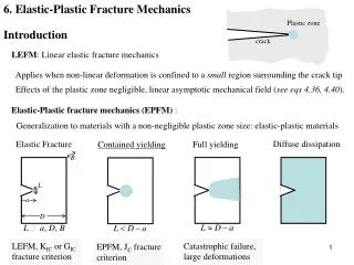
D Inner shells Outer shell “Sword-in-sheath” Fracture Multi-wall carbon nanotubes fracture in a “sword-in sheath” manner during tensile test. Cross-sectional area: : inter-layer separation of graphite, 0.34 nm
MWCNT Diameter Measurement Cantilever holders were designed to hold a shortened AFM chip for nanotube diameter measurement in TEM. AFM cantilevers (a) AFM chip holder model (c) Gatan TEM straining holder (model 654) (d) SEM and TEM images of a MWCNT fragment attached to an AFM tip. (b) An AFM chip in the AFM chip holder
Stress & Strain Measurements The whole tensile testing process was recorded by taking SEM images at each loading step.
MWCNT Tensile Testing Result Fracture Strength Elastic Modulus Average elastic modulus: ~ 910 GPa
Multiple Loading (Tube #6) (1) (2) (3)
Nanoparticle Chain Aggregates Stretching a chain Tensile Testing Contact Force Measurement • Carbon nanoparticle chain aggregates • Nanoparticle diameter: 25-35 nm • Chain length: ~ 2 m • Breaking Force: 42 25 nN • Tensile Strength: 40 -100 MPa • Elastic Modulus : 200 - 600 MPa • Particle Contact Force: 8 4 nN
L x x (x,y) s y Fx 0 Fy y F F(k),F(,k) complete and incomplete elliptic integral of first kind. k and 1 are obtained from angle 0 with following relationships: Nonlinearity: Large Deflection + Misalignment where Fx=Fsin and Fy=Fcos (Transformation; Converting to elliptic integrals)
Experimental Data Analysis • AFM cantilevers were used as force-sensing elements in our nanoscale tensile testing experiments on templated carbon nanotubes inside SEM. • Large deflection of the cantilever beam was encountered in the tests along with non-ideal alignment of the specimens. • The linear analysis underestimated the applied load up to 15 %.
Error in Linear Estimation Normalization Linear analysis Analytical analysis