Download
1 / 16
210 likes | 614 Vues
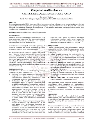
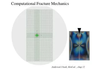
Computational Fracture Mechanics. Anderson’s book, third ed. , chap 12 . Elements of Theory. CF Shih, B. Moran and T. Nakamura, “Energy release rate along a three-dimensional crack front in a thermally stressed body”, International Journal of Fracture 30 (1986), pp. 79-102.

E N D
Computational Fracture Mechanics Anderson’s book, third ed. , chap 12
Elements of Theory CF Shih, B. Moran and T. Nakamura, “Energy release rate along a three-dimensional crack front in a thermally stressed body”, International Journal of Fracture30 (1986), pp. 79-102 Energy domain integral method: - Formulated by Shih et al. (1986): - Generalized definition of the J- integral (nonlinear materials, thermal strain, dynamic effects). - Relatively simple to implement numerically, very efficient. Finite element (FE) code ABAQUS version 6.5 ABAQUS: - suite of powerful engineering simulation programs - based on the finite element method - for simple linear analyses and most challenging nonlinear simulations
Abaqus 6.5 : products associated with Abaqus: Optional capabilities (offshore structures, design sensitivity calculations) Abaqus Standard : general-purpose analysis product that can treat a wide range of problems. Abaqus Explicit : intended for modeling brief, transient dynamic events (impact) uses an explicit dynamic finite element formulation. CAE : interactive, graphical environment allowing models to be created quickly. can be used for producing/ importing the geometry to be analyzed. is useful to monitor/control the analysis jobs and display the results (Viewer). creates input files (.inp) that will be processed by Abaqus standard. For detailssee the Getting Started Manual of Abaqus 6.5
Energy Domain Integral : In 2D, under quasistatic conditions, J may be expressed by The contour G surrounds the crack tip. The limit indicates that G shrinks onto the crack tip. n : unit outward normal to G. x1 , x2 Cartesian system q : unit vector in the virtual crack extension direction. w : strain energy density and, s : Cauchy stress tensor displacement gradient tensor H : Eshelby’s elastic energy-momentum tensor (for a non-linear elastic solid) For details see the Theory Manual of Abaqus 6.5, section 2.16
With q along x1 and the field quantities expressed in Cartesian components, i.e. The previous equation is not suitable for a numerical analysis of J. Thus, In indexed form, we obtain The expression of J (see eq. 6.45) is recovered with Transformation into a domain integral
Following Shih et al. (1986), m : outward normal on the closed contour :the surface traction on the crack faces. with Note that, A includes the crack-tip region as (*) A is a sufficiently smooth weighting function in the domain A. m = -n on G
(*) Derivation of the integral expression → Line integral along the closed contour enclosing the region A. = = 0 q 0 Noting that, since since
the J-integral is only defined by the limiting contour in A Introducing then the vector, Using the divergence theorem, the contour integral is converted into the domain integral • Under certain circumstances, H is divergence free, i.e. indicates the path independence of the J-integral. • In the general case of thermo-mechanical loading and with body forces and crack face tractions: or Using next the relationship, Contributions due to crack face tractions.
In Abaqus: - This integral is evaluated using ring elements surrounding the crack tip. Contour (i) 1 Crack 2 Exception: on midside nodes (if they exist) in the outer ring of elements - Different contours are created: First contour (1) = elements directly connected to crack-tip nodes. The second contour (2) are elements sharing nodes with the first, … etc Refined mesh nodes outside nodes inside 8-node quadratic plane strain element (CPE8)
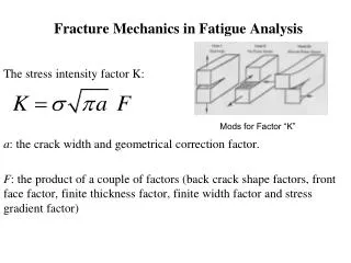
crack front at s J defined in the x1- x2 plane L T J-integral in three dimensions Local orthogonal Cartesian coordinates at the point s on the crack front: Point-wise value For a virtual crack advance l(s) in the plane of a 3D crack, L : length of the crack front under consideration. :surface element on a vanishingly small tubular surface enclosing the crack front along the length L.
Numerical application (bi-material interface): a = 40 mm y b = 100 mm a/b = 0.4 h = 100 mm x Remote loading: s = 1 MPa. • SEN specimen geometry (see annex III.1): s Material 1 and h/b = 1 2h a b Materials properties (Young’s modulus, Poisson’s ratio): Material 1: E1 = 3 GPa n1 = 0.35 Material 2 Material 2: E2 = 70 GPa n2 = 0.2 s Plane strain conditions.
Material 1 Material 2 • Typical mesh: Material 1= Material 2 Refined mesh around the crack tip Number of elements used: 1376 Type: CPE8 (plane strain)
Results: SIF given in • Ones checks that: for the isotropic case (i =1,2). (*) (*) same values on the contours 2-8
Relationship between J and the SIF’s for the bi-material configuration: H. Gao, M.Abbudi and D.M. Barnett, “Interfacial Crack-tip fields in anisotropic elastic solids thermally stressed body”, Journal of the Mechanics and Physics of Solids40 (1992), pp. 393-416 - For an interfacial crack between two dissimilar isotropic materials (plane strain), where and plane strain, i = 1,2 KI and KIIare defined here from a complex intensity factor, such that with - Extracted from the Theory Manual of Abaqus 6.5, section 2.16.2. Disagreement with the results of Smelser et al.