
Manufacturing Processes
E N D
Presentation Transcript
Manufacturing Processes Chap.19 Part B Sheet Metal Forming
Bending • One of the most common forming operations. • Used to form flanges, seams, corrugations or impart stiffness. • Outer fibers are in tension, inner fibers are in compression. (Fig. 16.16) • Outer width of a bend is smaller than inside width (Poisson effect).
Bend Allowance • Def.: Length of neutral axis in the bend. • Used to determine blank length prior to bending. • Position of neutral axis depends on bend radius and angle. Lb = a ( R + kT) a = bend angle (rads) T = sheet thickness R = bend radius k = constant (ideal case k = 0.5; reality: 0.3 < k <0.5)
Minimum Bend Radius • Def. Ratio at which crack appears on outer bend surface. • Expressed i.t.o. thickness (2T, 3T, etc.) • Interpretation: 3T = smallest radius to which sheet can be bent, without cracking, is 3 times its thickness. • Some typical values: • Aluminum 6T • Magnesium 13T • Soft, Low Carbon Steel 0.5T
Bendability • Anisotropy is important factor in bendability. • Cold rolling imparts directionality to fibers, impurities, inclusions. • Must cut sheet metal in proper direction prior to bending to minimize cracking at bend. • See Fig. 16.17a,b
Springback • Def.: The elastic recovery of metal after plastic deformation, once load is removed. • Calculated in terms or initial and final Radii. Ri / Rf = 4 (RiY / ET)3 - 3 (RiY/ET) + 1 (E = Young’s Modulus, Y = Material Yield Stress, Ri = Initial Radius, Rf = Final Radius, T = Sheet Thickness.) • Springback increases with increasing R/T ratio, Y, decreasing E. Can compensate by overbending the part.
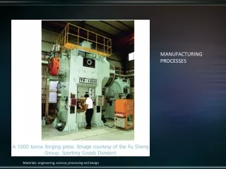
Bending Force • Can simplify by studying simple bending of a rectangular beam. • F :: f ( material strength, length of bend L, sheet thickness T, width of die opening W) • Neglects friction. P = kY LT2 / W • k depends on the type of die.
Bending Force • For V dies, P = (UTS) LT2 / W • where UTS = ultimate tensile strength of material. • Bending force goes from 0 to a maximum and then decreases as bend is completed, then increases when punch reaches end of stroke.
Bending / Forming Operations • Press Brake Forming • Used to easily bend metal with simple fixtures. • Tooling is simple and adaptable to a wide variety of shapes. • A press brake is used to bend long sheets (20+ ’). See Fig. 16.23. • Roll Bending • plates are bent using a set of 3 or more rolls.See Fig. 16.22
Bending / Forming Operations • Beading • Edge of sheet is bent into a cavity to form a bead. See fig. 16.24. • Bead gives stiffness to part, improves appearance and removes sharp edges. • Flanging • Bending of sheet metal edges usually to 90 degree angles. • Dimpling • When a hole is punched and then formed into a flange.
Bending / Forming Operations • Hemming • When a sheet is folded over itself. • Hem gives stiffness to part, improves appearance and removes sharp edges. • Roll Forming • Used for forming long lengths of sheet metal and for large production runs. • Metal is bent in stakes by passing it through a series of rolls. • Typical products include channels, gutters, door frames. (Figs. 16.26)
Bending / Forming Operations • Tube Bending • Requires special tooling to avoid buckling and folding. • Old method is to pack inside with sand and bend in a fixture. • Sand prevents tube from buckling. Once bent, sand is taken out.
Bending / Forming Operations • Bulging • Tubular or conical part is placed in split female die. • A polyurethane plug is pressed with a punch against the inside of the part. • Plug expands and forms metal against die. • Punch retracts and plug recovers its original shape. • Examples: coffee pots, other containers. See Fig. 16.28.
Deep Drawing • Used for cylindrical or box-shaped parts. • Typical products include pots, pans, soda cans, kitchen sinks. • Sheet metal blank is placed over circular die. • Blank is held with blank holder. • Punch forces die into cavity, forming a cup. • See Fig. 16.31
Deep Drawing • Some important variables: • clearance, blank diameter / punch diameter, punch corner radius. • Drawing tends to produce hoop (compressive circumferential) stresses in flange. • Tend to wrinkle part during drawing. • Can reduce by controlling blank holder force as a function of punch travel. • Elongation of metal will cause cup wall to thin. Can tear if excessive.
Drawing Practices • Blankholder pressure = ~1% of Yield Strength and UTS of sheet metal. • If too high -> tearing. If too low-> wrinkling. • Clearances: allow 7-14% of sheet thickness. • Use drawbeads to control flow of blank into die cavity. • Drawbeads restrict flow of sheet metal by bending/unbending it. (See illustration). • Drawbeads also help reduce blankholder forces.
Rubber Forming & Spinning • Rubber Forming • One of the dies in a set is flexible (polyurethane material). • Good due to their resistance to abrasion, long fatigue life. • See Fig. 16.38 (the Guerin Process). • Spinning • Involves forming axisymmetric parts over a mandrel with the use of tools & rollers. • Three types: conventional, shear, tube spinning.
Conventional Spinning • Circular blank (flat or preformed) is held against a mandrel and rotated. • Tool presses against blank following the contour of the mandrel. • Can be manual or CNC controlled. • May require several passes. • See Fig. 16.40.
Shear Spinning • Can produce axisymmetric shape. • Maintains part max diameter while reducing its thickness. • Rocket engine casings, missile nose cones are typical applications. • Generates intense heat and must be cooled during spinning. • See Fig. 16.41 .
High-Rate Energy Forming (HERF) • Deformation of metal via the application of a large amount of energy in a short period of time. • Some metals favor this type of deformation. • Can deform very large pieces quite easily and inexpensively. • Very little springback-related problems. • (very high compressive stresses imparted) • (slight deformation of the die occurs due to the ultra-high pressure, overforming the part).
Explosive Forming • Can use controlled detonations as a source of energy in metal forming. • See fig. 16.44 • Blank is secured over a die. • Assembly is placed in water tank. • Air in die cavity is extracted. • Charge is placed at a distance and blasted. • Shock wave yields enough pressure to form sheet metal.