Push-Pull Operation for Detector and Magnet Infrastructures: Challenges and Solutions
150 likes | 186 Vues
Explore the specific requirements for detector and accelerator systems during switch-over operations. Learn about magnet infrastructures, cavern layouts, and solutions for powering and protection in this detailed overview.

Push-Pull Operation for Detector and Magnet Infrastructures: Challenges and Solutions
E N D
Presentation Transcript
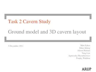
Magnet Infrastructures and Cavern Layout CLIC Detector WG5, April 1st 2010 Andrea Gaddi Physics Dept. - CERN
Introduction • The push-pull mode of operation sets specific requirements and challenges for many systems of detector and accelerator, in particular for: • the IR magnets • the cryogenics, vacuum and powering systems of detector magnet • machine and detector alignment system • beam-line shielding • The EA design shall allow the fastest and safest detector switch-over, including: • detector moving • services reconnections • shielding re-arrangements • machine and detector re-alignment. • The actual target is to perform the switch-over in a fewdays. • The push-pull operation includes time from the switch-off the beam until the moment when luminosity is restored to 70% level and at the same energy, after the detector exchange (cfr. ILC).
Magnet infrastructures & push-pull scenario The two most challenging magnet services are the cryogenics & vacuum system and the powering & protection one. The He liquifier is an heavy and delicate components that cannot move with the detector, neither sit too close, due to the magnetic stray field. Its ideal location is the side service cavern, along with the fore vacuum pumps, that are noisy in terms of vibration and need easy access for maintenance. The power supply, and its associated breakers, is also a huge and heavy component whose location is better chosen in the service cavern. On the contrary, the dump resistors protecting the coil, should stay as close as possible to the magnet, but consideration on the total energy (> 1GJ) dissipated in the cavern may lead to move them away from the detector.
Cavern layout Cable-chain
Flexible cryo & vacuum lines The detector solenoid has to stay cold during the push-pull period, i.e. liquid Helium and has to be guaranteed via flexible transfer lines. Vacuum inside the coil cryostat could be kept by simple cryo-pumping during push-pull, but a flexible rough vacuum line is necessary anyhow. CMS has 30m long rigid cryo transfer line, vacuum insulated + 50m long rigid F230mm primary vacuum line (10-3 mbar) Not applicable to push-pull. Flexible cryolines have been successfully installed to cool Atlas Endcap Toroids LHe lines diameter 58mm Outer shielding 110mm Vacuum envelope 143mm SiD foresees a flexible cryoline F160mm, vacuum insulated
Flexible HTS bus-bars • Despite the fact that during push-pull, the detector magnet is obviously off, • a permanent connection of the solenoid power supply to the coil current leads • would save precious time. This line shall be able to carry 20kA in a self-field • of about 0.6T, over a length of some 60m. A flexible resistive line would take • too much space in the cavern and have a significant voltage drop DV (in addition • to the power dissipated P=DVxI). • CERN is actually developing the design of a semi-flexible, vacuum insulated, • HTS (MgB2) line for the LHC upgrade. • The characteristics of this powering line are the following: • Nominal current: 110kA at 20K and 0.8T • Maximum current: 130kA at 20K and 0.8T • Cooling: GHe, from 5 to 20K • Length: 100m • Vacuum envelope: F90mm • Minimum bending radius: 1.5m
Proposal for powering lines : flexible HTS bus-bars Prototypes of the multi-cables HTS powering line (courtesy A. Ballarino, CERN-TE Dept.)
Proposal for dump-system : compact water-cooled resistors Total stored magnetic energy ≈ 2.50 GJ Energy extracted by the dumping system ≈ 1.25 GJ Solenoid reference current (I) ≈ 20 kA Solenoid inductance (L= 2E/I2) ≈ 12.5 H Dump resistance (R) ≈ 30 m Discharge voltage ≈ 300 V wrt ground Peak discharge power (Ppeak=I2R) ≈ 12 MW Discharge time constant (t=L/R) ≈ 416 s
Stray field considerations • Requirement for the magnetic field outside of detector is an important factor which defines the amount of iron in the detector (or degree of compensation for endcap hybrid-design). • Effects of any field outside of detectors on the beam shall be corrected, and the requirements should come from human safety factor, from the limit of field map distortion due to off-beamline detector and from effects on cavern equipment. • Field on any external surface of on-beamline detector shall be less than 2kGs, while its field in non-restricted area (including near the off-beamline detector) to be less than 100Gs (ILC requirements). • The magnetic field effect from the off-beamline detector onto the on-beamline detector must limit distortion of magnetic field map of the latter to less than 0.01% anywhere inside its tracking volume (ILC requirement).
Conclusion & work-plan towards the CDR. • The push-pull scenario leads to an integrated design of detectors infrastructures. • A compromise between on-board services and a remote “service block” has to be found, making use of cable-chains that assure permanent connections with the service block, allowing a smooth movement of the detector during the push-pull operation. We will focus our work on this. • Cryogenics and vacuum flexible lines have been already successfully used at Atlas. Need to be adapted to CLIC detector magnet. An existing R&D program for a HTS powering line for LHC upgrade could give good indications for a 20kA HTS line cooled with GHe between 5 and 20K, to be employed for detector magnet power-lines. • The problem of a compact on-board dump-system could be solved with a water-cooled resistor-bench. A 1/10 scale prototype could be useful to validate our simulations. • Integration of magnet services with cavern layout requires a closer collaboration with civil engineering group. • The effects of the stray-field have to be carefully looked. Any effort to limit the stray-field via an optimized yoke design has to be pursued.