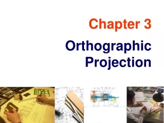
3-D PROJECTION
ERT 249 C omputer Aided Design (CAD) For Biosystem Engineering. 3-D PROJECTION. PREPARED BY: SAMERA BINTI SAMSUDDIN SAH. 3D PROJECTION. Three different types of 3-D projections are available in most CAD software: isometric, trimetric, and perspective.

3-D PROJECTION
E N D
Presentation Transcript
ERT 249Computer Aided Design (CAD)For Biosystem Engineering 3-D PROJECTION PREPARED BY: SAMERA BINTI SAMSUDDIN SAH
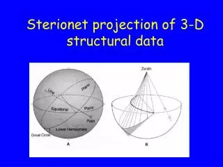
3D PROJECTION • Three different types of 3-D projections are available in most CAD software: • isometric, • trimetric, and • perspective. • These three views of a cube are shown in figure below.
In all three cases, these 3-D projections represent all three dimensions of the cube in a single planar image. • Although it is clear in all three cases that the object is a cube, each type of 3-D projection has its advantages and disadvantages.
1. ISOMETRIC PROJECTION • The isometricprojection has a standard orientation that makes it the typical projection used in CAD. • In an isometric projection, the width and depth dimensions are sketched at 30° above horizontal. • This results in the three angles at the upper front corner of the cube being equal to 120°. • The three sides of the cube are also equal, leading to the term iso (equal) -metric (measure).
Isometric drawings work quite well for objects of limited depth. • However, an isometric drawing distorts the object when the depth is significant. • In this case, a pictorial perspective drawing is better.
2. TRIMETRIC PROJECTION • In general, the trimetric projection offers more flexibility in orienting the object in space. • The width and depth dimensions are at arbitrary angles to the horizontal, and the three angles at the upper front corner of the cube are unequal.
This makes the three sides of the cube each have a different length as measured in the plane of the drawing; hence the name tri-metric. • In most CAD software, the trimetric projection fixes one side along a horizontal line and tips the cube forward.
3. PERSPECTIVE PROJECTION • A simply perspective (pictorial perspective) projection is drawn so that parallel lines converge in the distances, unlike isometric or trimetric projections where parallel lines remain parallel. • A perspective projection is quite useful in providing a realistic image of an object when the object spans a long distance such as the view of a bridge or aircraft from one end. • Generally, small manufactured objects are adequately represented by isometric or trimetric views.
Two types of pictorial sketches are used frequently in freehand sketching: • isometric and • oblique. • The isometric projection is often used in freehand sketching because it is relatively easy to create a realistic sketch of an object. • But the oblique projection is usually even easier to sketch. • The figure compares an isometric and an oblique projection of a cube with a hole in it. • oblique freehand sketching easier than isometric sketching.