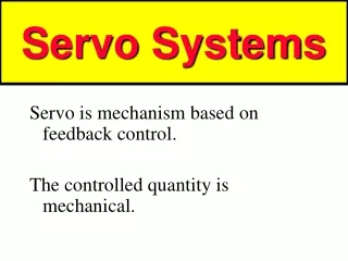
Servo Positioning
Servo Positioning. Direction Determined by the width of the pulse Distance Each pulse causes the servo to rotate a small amount Speed Maximum at 1.3 and 1.7 ms. Decreases as approaches 1.5 ms. Basic Boe-Bot Maneuvers. Page 111. Controlling Distance.

Servo Positioning
E N D
Presentation Transcript
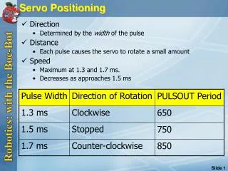
Servo Positioning • Direction • Determined by the width of the pulse • Distance • Each pulse causes the servo to rotate a small amount • Speed • Maximum at 1.3 and 1.7 ms. • Decreases as approaches 1.5 ms
Basic Boe-Bot Maneuvers Page 111
Controlling Distance • Run "BoeBotForwardThreeSeconds.bs2" • Follow the instructions on p. 118 to make the Boe-Bot go half as far forward • Add code to make the Boe-Bot go backward, left, and right, as shown on pages 119-120 FOR counter = 1 TO 122 PULSOUT 13, 850 PULSOUT 12, 650 PAUSE 20 NEXT
Example Program: ForwardLeftRightBackward.bs2 Page 127 – 128 Forward Rotate Right Rotate Left Backward
Building Complex Maneuvers in EEPROM Page 147
EEPROM Navigation Page 149 Page 152 Page 150
Projects 1 m 1 m 1 m 1 m Page 159
Tactile Navigation with Whiskers Page 166 Page 167 Page 167
Building the Whiskers Page 168 Page 169 Page 172
Testing the Whiskers • Run "TestWhiskers.bs2" p.173 • Press on each whisker and examine the Debug Terminal output. • Each whisker should display 1 when not pressed, 0 when pressed. • Position the whisker wires to make good contact with the headers DEBUG "WHISKER STATES", CR, "Left Right", CR, "------ ------" DO DEBUG CRSRXY, 0, 3, "P5 = ", BIN1 IN5, " P7 = ", BIN1 IN7 PAUSE 50 LOOP
Field Testing the Whiskers – Add LEDs Page 174 Page 175 Page 177
Navigation With Whiskers • Run "Roaming with Whiskers.bs2" • Compare with pushbuttons exercise from the previous day DO IF (IN5 = 0) AND (IN7 = 0) THEN ' Both whiskers detect obstacle GOSUB Back_Up ' Back up & U-turn (left twice) GOSUB Turn_Left GOSUB Turn_Left ELSEIF (IN5 = 0) THEN ' Left whisker contacts GOSUB Back_Up ' Back up & turn right GOSUB Turn_Right ELSEIF (IN7 = 0) THEN ' Right whisker contacts GOSUB Back_Up ' Back up & turn left GOSUB Turn_Left ELSE ' Both whiskers 1, no contacts GOSUB Forward_Pulse ' Apply a forward pulse ENDIF ' and check again LOOP
Light Sensitive Navigation with Photoresistors Page 193 Page 195
Navigating with Infrared Headlights Page 236 Page 237 Page 237