Download
1 / 29
290 likes | 296 Vues
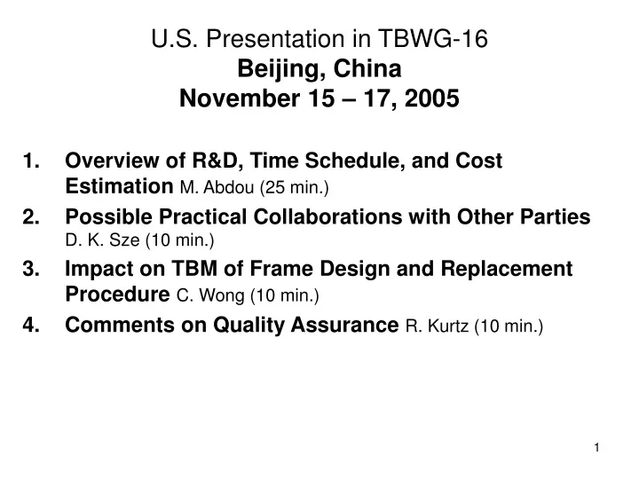
U.S. Presentation in TBWG-16 Beijing, China November 15 – 17, 2005. Overview of R&D, Time Schedule, and Cost Estimation M. Abdou (25 min.) Possible Practical Collaborations with Other Parties D. K. Sze (10 min.) Impact on TBM of Frame Design and Replacement Procedure C. Wong (10 min.)

E N D
U.S. Presentation in TBWG-16Beijing, ChinaNovember 15 – 17, 2005 Overview of R&D, Time Schedule, and Cost Estimation M. Abdou (25 min.) Possible Practical Collaborations with Other Parties D. K. Sze (10 min.) Impact on TBM of Frame Design and Replacement Procedure C. Wong (10 min.) Comments on Quality Assurance R. Kurtz (10 min.)
Overview of US ITER TBM R&D, Time Schedule, and Cost Estimation Mohamed Abdou, Alice Ying, Neil Morley, Clement Wong, Tom Mann, Dai-Kai Sze, Mike Ulrickson, and the US ITER TBM Team TBWG-16 Detailed information is available at http://www.fusion.ucla.edu/ITER-TBM Note this information is being continually updated and refined.
US ITER TBM Program: Selected Concepts 1. The Dual-Coolant Pb-17Li Liquid Breeder Blanket concept with self-cooled Pb-Li breeding zone and flow channel inserts (FCIs) as MHD and thermal insulator -- Innovative concept that provides “pathway” to higher outlettemperature/higher thermal efficiency while using ferritic steel. -- Plan an independent DCLL TBM that will occupy half an ITER test port with corresponding ancillary equipment -- Work closely with any Parties interested in this or similar concepts 2. The Helium-Cooled Solid Breeder Blanket concept with ferritic steel structure and beryllium neutron multiplier, but without an independent TBM -- Support EU and Japan efforts using their TBM structure & ancillary equipment -- Contribute unit cell /submodule test articles that focus on particular technical issues
A Detailed TBM Planning and Costing Activity for the US TBM Program has been requested by the DOE • Planning will be for the US Reference Scenarios: • DCLL TBM with PbLi exit temperature of 470ºC and a series of TBM that occupy half a port. • HCCB submodule that has a size of 1/3 of one-half port in cooperation with the EU or Japan • Detailed planning and cost is for a 10 year period between now and the shipment of the TBM deliverables in 2015 for DAY ONE ITER operation. • The cost is the total cost for the TBM project including R&D, design, engineering, fabrication, qualification, etc., as well as the cost of interface with ITER and other parties. • The R&D Cost includes all costs related to the Reference Scenarios that occur within the next 10 year period whether they are related to the first (Day ONE) Test Articles or subsequent test articles. • Cost of the deliverables includes only the cost of the First Test Article and associated equipment (See Project Deliverables slide).
Primary He Coolant Loop TCWS Secondary He Coolant Loop TCWS Test Port Pb-Li Primary Coolant Loop Transporter, Port Cell Area US Test Blanket “Project” Deliverables Based on Reference Scenario Parameters • US DCLL • Test Module • Helium Flow Loop (primary) • PbLi Flow Loop • Tritium Processing Systems • Secondary Helium Flow Loop (and Heat Exchanger for PbLi Flow Loop) • US HCCB • Test Submodule • Ancillary Equipments (primary helium flow conditioners, measuring systems for helium, tritium, and test submodule) DCLL TBM coolant circuits,Red-dotedcircuit shows the primary He loop cooling the first wall and all FS structures, Blue-dash circuit shows the Pb-Li loop and theGreen-dashcircuit shows the secondary helium loop.
US ITER TBM Costing Activity Milestones • 12-Aug-05 Costing Activity Initiated • 31-Aug-05 WBS established for Level 6 and lower Responsible persons for Level 6 and lower assigned • 7-Sep-05 WBS for Level 6 and lower revised • 9-Sep-05 Conceptual design summaries for DCLL and HCCB issued • 6-Oct-05 Initial schedule and base cost estimate for WBS level 6 of DCLL and HCCB • 27-Oct-05 Initial schedule and base cost estimate for engineering design, procurement/fabrication, and ancillary equipment • 7-Nov-05 R&D decision criteria established • 30-Nov-05 Complete revised schedule and cost estimate for WBS level 6 and lower (include contingency factor) • 12-14 Dec-05 “Physical” Meeting (all information about costing will be presented and discussed) • 16-Dec-05 R&D priorities finalized • 13-Jan-06 Initial Draft Costing Activity Report Due • 15-Feb-06 Complete Draft of Final Costing Activity Report • 22-23 Feb-06 Physical meeting (internal review of draft report) • 1-Mar-06 Complete incorporating comments into the Report • 15-Mar-06 Send Final TBM Cost Estimate Report to DOE • 28-Mar-06 “External” review
US DCLL TBM Reference Scenario Conditions TBM Reference Scenario FS Tmax ≤ 550° C FS/PbLi < 500° C SiC/PbLi < 500° C SiC Tmax < 500° C He < 450° C PbLi ≤ 470° C • Notes: • DCLL features will be tested at PbLi temperatures compatible with ferritic steel (500C). He and PbLi flowrate, and inlet and outlet temperature, will be varied depending on experiment underway, but these limits will not be exceeded • External piping material for Helium system will be austenitic steel (transition element required) • External piping material for the PbLi has not yet been decided, but likely to be a commercial ferritic/martensitic steel up to the HX (Cutting/rewelding technique required)
US Test Blanket Project Organized by Subsystem and Deliverables
Most Work Breakdown Structure Elements are further broken down into the following subcategories: • Administration • R&D • Engineering • Preliminary Design • Detailed Design • Fabrication Support • Fabrication/procurement • Assembly, testing, & installation
US strategy for ITER testing of the DCLL Blanket and First Wall Concept • Develop and deploy a series (~4) of vertical half-port DCLL-TBMs during the period of the first 10 years of ITER operation with • Test articles from day one of ITER operation with specific testing goals and diagnostic systems • Associated ancillary equipment systems • in a transporter behind the bioshield and in space in the TCWS and tritium buildings • using bypass PbLi flow to keep temperature of ancillary equipment below material limits • Develop international collaboration on PbLi systems to the maximal extent
Electromagnetic/Structural (EM/S)TBM (for Hydrogen Phase) Testing Goals • Validate general TBM structure and design • Measure forces and the mechanical response of the TBM structure to transient EM loads • Determine ferromagnetic and MHD flow perturbation of ITER fields • Measure thermal and particle load effects on plasma facing surface (Be) and FW structure/heat sink Information in the early HH phase can be used: • to modify designs of subsequent TBMs to be deployed in the later DT phase • for ITER DT Licensing. • Establish performance baseline and operational experience of the TBM and ancillary systems • Integration of control systems and diagnostics with ITER systems • Demonstration of required subsystems and port integration • Demonstration of remote handling procedures • Measurement of thermal time constants and heat loss • Measurement of tritium (hydrogen) permeation characteristics • Testing heating/filling/draining/remelting and accident response procedures • Perform initial studies of MHD effects and Flow Channel Insert performance • MHD flow distribution (manifold design, multichannel effects) • 3D pressure drop (toroidal field and toroidal + true poloidal field) • FCI performance changes as a function LM exposure time • FCI response to loading from EM events (water hammer, transient eddy current forces) • Map ITER field in TBM area
DCLL Test Module Fabrication Schedule Summary (note: schedules are evolving) *Prototype may or may not be full scale
Purposes of R&D activities in a “project” are to reduce risk • Risk that the experimental device will negatively impact ITER • plant safety, licensing • operation schedule • Risk that TBM experiments will not achieve experimental mission • Understanding of phenomena and modeling capability is insufficient to interpret or utilize data • Failures in diagnostics or large inaccuracies in measurements give incomplete or poor data • Unanticipated system performance leads to irrelevant or unquantifiable operating conditions
Main DCLL TBM R&D Areas Identified in the US Activity. Several are common issues of interest to all Parties
DCLL Test Module R&D Schedule Summary (note: schedules and R&D tasks are evolving)
Some R&D area highlights: Thermofluid – MHD • Thermofluid – MHD is an important class of issues for the DCLL design, operation and safety • Several R&D subtasks are being planned • Continued model development: 3D-HIMAG and other research codes needed to predict basic performance of DCLL and to utilize/interpret TBM experimental data • Experiments on basic FCI performance: 3D pressure drop, flow development, effect of / need for pressure equalization holes, overlap regions, etc. • Experiments on manifolds design: needed to explore range of achievable flow uniformity under various operating conditions • Partially integrated MHD flow tests on flow mockups Example: Effect of FCI pressure equalization gap on Hartmann wall side, SiC=20
2.0 Tritium pressure above PbLi (Pa) 1.5 1.0 0.5 Number of pulses 0.0 0 10 20 30 40 50 Some R&D area highlights: Tritium Inventory and Permeation Modeling • Simulations have lead to a new strategy for tritium control • Swept secondary containment around transporter cask and TCWS skid for controlling leaked or permeated tritium • More aggressive permeator development to reduce tritium partial pressure in PbLi • Swept secondary containment around all PbLi (and He) piping • Operation at lower He/PbLi temperatures if ITER limit is approached TMAP model and resultant tritium pressure for an example DCLL case
An Idea: Virtual TBM • Better integration and management of codes used for predicting TBM conditions and interpreting TBM experiments • CAD • MCNP • HIMAG • TMAP • ANSYS • RELAP • … • Experience with CAD/MCNP should just be the start
Rough DCLL TBM Cost Estimate Summary Covering the next 10 years(Subject to revision in detailed evaluation of costs) • Design, analysis and DCLL TBM and systems fabrication • rough cost estimate is XXX • some key costs still not included • Prioritizing and trade-off assessment activity underway • Risk assessment activity underway
Ceramic Breeder Test SubmoduleInserting “US” unit cells into the EU HCPB structural box Electromagnetics/Neutronics unit cell design Unit (mm)
Main HCCB Test Sub-Module R&D Areas Identified in the Activity
HCCB Test Sub-Module Schedule Summary (note: schedules and R&D tasks are evolving)
Rough HCCB TBM Cost Estimate Summary Covering the next 10 years(Subject to revision in detailed evaluation of costs) • Engineering Design Activities: ~$XXX • Fabrication of 1st series of unit cells ~$XXX
Categorizing R&D Tasks • A system needs to be established to categorize R&D tasks to give a cost range • Simple rating system being tried in the US: • E = Essential for the qualification and successful execution of the TBM experiment, and no other party is doing it • I = Important for the qualification and successful execution of the TBM experiment, or Essential but is definitely being done by another party • D = Desirable but the risk is acceptable if not performed • According to this system: International effort affects US prioritization
Some initial conclusions(that some have already realized, but all need to face) • TBMs are generally much more expensive than initial estimates might show • Many hidden expenses will continue to be discovered • Undefined elements of ITER QA/licensing requirements can impact cost significantly (~>10%) • R&D efforts are a large portion of costs • They must be scrutinized and prioritized • R&D activities mostly address areas of interest to other Parties • Tested full scale prototypes are likely necessary to avoid failures in first years of operation that jeopardize mission of validating DT phase TBM • There is very little time left if subscale mockups and prototypes are to be attempted.
TBWG should identify and coordinate effort on key, common, R&D areas • Suggestion, For each common R&D area, one or two parties (depending on issue difficulty and criticality) should “volunteer” to do the research, and share the results • Be layer joining to FS • Tritium extraction and cleanup in He purge and coolants • Common diagnostic sensors and controllers • Common test and qualification tests and test facilities • Virtual TBM simulation capabilities • FS technology (joining, shaping, in-situ rewelding, irradiation database) • FS to Austenitic Steel Transition Sections • PbLi/Water hydrogen generation (all PbLi systems with volume > 280 liters) (Another US Presentation will elaborate on practical possibilities…) • Cooperation on R&D issues is the first step to cooperative test programs – once common needs and purposes are clearly evident to the parties