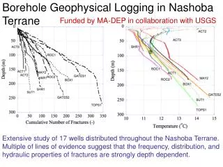
Download
1 / 21
280 likes | 639 Vues
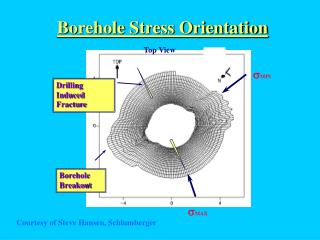
Borehole Stress Orientation. Top View. s MIN. Drilling Induced Fracture. Borehole Breakout. s MAX. Courtesy of Steve Hansen, Schlumberger. Types of Directional Drilling for Fractures. Nelson & Serra (1995). Courtesy of CSPE. Potential Drilling Directions on Folds.

E N D
Borehole Stress Orientation Top View sMIN Drilling Induced Fracture Borehole Breakout sMAX Courtesy of Steve Hansen, Schlumberger
Types of Directional Drilling for Fractures Nelson & Serra (1995) Courtesy of CSPE
Potential Drilling Directions on Folds Nelson et.al. (1987a) Courtesy of CSPE
Fracture Spacing & Drilling Direction After Nolen-Hoeksema & Howard (1987) Courtesy of AAPG
Drilling Direction Nomograph Nolen-Hoeksema & Howard (1987) Courtesy of AAPG
Bedding/Fracture/Well Rotation Joubert & Rice (1997) unrotated rotated
UBI FMI UBI vs. FMI UBI Shows Topography FMI Shows Resistivity Courtesy of Steve Hansen, Schlumberger
Quantitative Fracture Analysis Polar projections of fold and fault related fractures with dip of 300 deg NW After removing structural bedding dip, fractures trend clearly NW-SE and to perpendicular to bedding.
N N before bedding rotation after bedding rotation Rotated Fracture Poles equal area, lower hemisphere, stereonets. fracture poles for all 9 wells ~ 1700 poles Joubert & Rice (1997)
Equation - Fracture Intercept Rate The fracture frequency in any arbitrary direction is the sum of: i th fracture - occurrence of i th fracture, - the cosine of the angle between the normal intercept rate direction of the i th fracture, over all fractures.
1 2 Fracture 1 Fracture 2 Occurrence Weighting (Lacazette 1990) Joubert & Rice (1997) Fracture 2 is less likely to be intercepted by the drill hole than fracture 1 - as the angle of the normal approaches 90 deg. W increases. W1 < W2 Drill Hole
Occurrence Corrected Rose Diagrams rotated raw fracture planes occurrence weighted fracture planes Joubert & Rice (1997)
Intercept Rate Joubert & Rice (1997) NORTH Polar chart showing number of fractures intercepted per meter for different drilling directions - (bedding rotated flat). 1.2 1 0.8 0.6 0.4 0.2 WEST EAST 0 horizontal 15 deg. 30 deg. 45 deg. 60 deg. Well #1 75 deg. vertical SOUTH
Aperture Variation on Rose Diagram N maximum aperture minimum aperture Joubert & Rice (1997)
Fracture Aperture Courtesyof Steve Hansen, Schlumberger
Equation - Flow Intercept Rate - fracture aperture of the i th fracture Joubert & Rice (1997)
NORTH WEST EAST HORZ. 15 DEG. 30 45 60 75 SOUTH 90 Flow Intercept Rate Joubert & Rice (1997)
120 well # 100 1 80 2 3 4 60 5 % of maximum flow 6 40 7 8 9 20 0 horz. 15 30 45 60 75 Vert. inclination angle relative to bedding Calculated Horizontal vs Vertical Drilling Drilling at low angles to bedding makes a good well Triassic Carbonate Reservoirs, Northern British Columbia, Canada From Joubert & Rice (1997)
Preferential directional alignment of elastic properties due to regional stress fields Horizontal anisotropy - uniform laterally but not vertically (transversely isotropic with a vertical axis of symmetry) Vertical anisotropy - uniform vertically but not laterally (transversely isotropic with a horizontal axis of symmetry) Shear waves travel faster along axis of symmetry Shear Anisotropy
Fracture-induced elastic anisotropy can be detected through shear-wave splitting, or birefringence Shear waves split into fast and slow polarizations Data are analyzed for orientation and degree of anisotropy indicated by the amount of birefringence Fast shear polarization direction relates to fracture orientation Shear Wave Birefringence