Timing Event-driven simulation
ECE 545 Lecture 8. Timing Event-driven simulation. Sources. A. Deway, Analysis and Design of Digital Systems with VHDL, Chapters 15, VHDL Technology M. Abramovici, M. Breuer, A. Friedman Chapter 3.10, Gate-Level Event Driven Simulation P. Ashenden, The Designer’s Guide to VHDL,

Timing Event-driven simulation
E N D
Presentation Transcript
ECE 545 Lecture 8 TimingEvent-driven simulation ECE 545 – Introduction to VHDL
Sources • A. Deway, Analysis and Design of Digital • Systems with VHDL, • Chapters 15, VHDL Technology • M. Abramovici, M. Breuer, A. Friedman • Chapter 3.10, Gate-Level Event Driven Simulation • P. Ashenden, The Designer’s Guide to VHDL, • Chapter 5.3 • Signal Attributes • Delta Delays • Transport and Inertial Delay Mechanisms ECE 545 – Introduction to VHDL
Timing of digital circuits ECE 545 – Introduction to VHDL
Timing Characteristics of Combinational Circuits LUT LUT LUT tp LUT tp routing Total propagation delay through combinational logic • Combinational Circuits Are Characterized by Propagation Delays • through logic components (gates, LUTs) • through interconnects (routing delays) ECE 545 – Introduction to VHDL
Timing Characteristics of Combinational Circuits (2) • Total Propagation Delay of Logic Depends on the Number of Logic Levels and Delays of Logic Components • Number of logic levels is the number of logic components (gates, LUTs) the signal propagates through • Routing Delays Depend on: • Length of interconnects • Fanout ECE 545 – Introduction to VHDL
Timing Characteristics of Combinational Circuits (3) LUT LUT LUT LUT • Fanout – Number of Inputs Connected to One Output • Each inputs has its capacitance • Fast switching of outputs with high fanout requires higher currents and strong drivers ECE 545 – Introduction to VHDL
Timing Characteristics of Combinational Circuits (4) • In Current Technologies Routing Delays Make 50-70% of the Total Propagation Delays ECE 545 – Introduction to VHDL
Timing Characteristics of Sequential Circuits (1) • Timing Features of Flip-flops • Setup time tS – minimum time the input has to be stable before the rising edge of the clock • Hold time tH – minimum time the input has to be stable after the rising edge of the clock • Propagation delay tP – time to propagate input to output after the rising edge of the clock ECE 545 – Introduction to VHDL
Timing Characteristics of Sequential Circuits (2) clk clk D tS tH D Q Q tP Input D must remain stable during this interval Input D can freely change during this interval ECE 545 – Introduction to VHDL
Critical Path (1) tP logic out in clk D D Q Q tCritical = tP FF + tPlogic + tS FF • Critical Path – The Longest Path From Outputs of Registers to Inputs of Registers ECE 545 – Introduction to VHDL
Critical Path (2) • Min. Clock Period = Length of The Critical Path • Max. Clock Frequency = 1 / Min. Clock Period ECE 545 – Introduction to VHDL
Clock Jitter • Rising Edge of The Clock Does Not Occur Precisely Periodically • May cause faults in the circuit clk ECE 545 – Introduction to VHDL
Clock Skew out in clk delay out in D D Q Q D D Q Q clk delay • Rising Edge of the Clock Does Not Arrive at Clock Inputs of All Flip-flops at The Same Time ECE 545 – Introduction to VHDL
Dealing With Clock Problems • Use Only Dedicated Clock Nets for Clock Signals • Do Not Put Any Logic in Clock Nets ECE 545 – Introduction to VHDL
Specifying time in VHDL ECE 545 – Introduction to VHDL
Physical data types Types representing physical quantities, such as time, voltage, capacitance, etc. are referred in VHDL as physical data types. TIME is the only predefined physical data type. Value of the physical data type is called a physical literal. ECE 545 – Introduction to VHDL
Time values (physical literals) - Examples 7 ns 1 min min 10.65 us 10.65 fs Numeric value Space Unit of time (dimension) ECE 545 – Introduction to VHDL
TIME values Numeric value can be an integer or a floating point number. Numeric value is optional. If not given, 1 is implied. Numeric value and dimension MUST be separated by a space. ECE 545 – Introduction to VHDL
Units of time Unit Definition Base Unit fs femtoseconds (10-15 seconds) Derived Units ps picoseconds (10-12 seconds) ns nanoseconds (10-9 seconds) us microseconds (10-6 seconds) ms miliseconds (10-3 seconds) sec seconds min minutes (60 seconds) hr hours (3600 seconds) ECE 545 – Introduction to VHDL
Values of the type TIME Value of a physical literal is defined in terms of integral multiples of the base unit, e.g. 10.65 us = 10,650,000,000 fs 10.65 fs = 10 fs Smallest available resolution in VHDL is 1 fs. Smallest available resolution in simulation can be set using a simulator command or parameter. ECE 545 – Introduction to VHDL
Arithmetic operations on values of the type TIME Examples: 7 ns + 10 ns = 17 ns 1.2 ns – 12.6 ps = 1187400 fs 5 ns * 4.3 = 21.5 ns 20 ns / 5ns = 4 ECE 545 – Introduction to VHDL
Propagation delay in VHDL ECE 545 – Introduction to VHDL
Propagation delay in VHDL - Example entity MAJORITY is port (A_IN, B_IN, C_IN : in STD_LOGIC; Z_OUT : out STD_LOGIC); end MAJORITY; architecture DATA_FLOW of MAJORITY is begin Z_OUT <= (not A_IN and B_IN and C_IN) or (A_IN andnot B_IN and C_IN) or (A_IN and B_IN and not C_IN) or (A_IN and B_IN and C_IN) after 20 ns; end DATA_FLOW; ECE 545 – Introduction to VHDL
Propagation delay - Example ECE 545 – Introduction to VHDL
MLU: Block Diagram ECE 545 – Introduction to VHDL
MLU - Architecture Body – Example 1 begin A1<=not A after 6 nswhen (NEG_A='1') else Aafter 5 ns; B1<=not B after 6 nswhen (NEG_B='1') else Bafter 5 ns; Y<=not Y1 after 6 nswhen (NEG_Y='1') else Y1after 5 ns; MUX_0<=A1 and B1after 3 ns; MUX_1<=A1 or B1after 3 ns; MUX_2<=A1 xor B1after 4 ns; MUX_3<=A1 xnor B1after 5 ns; L<=L1 & L0; with (L) select Y1<=MUX_0 after 7 nswhen "00", MUX_1 after 6 nswhen "01", MUX_2 after 8 nswhen "10", MUX_3 after 7 nswhen others; end MLU_DATAFLOW; ECE 545 – Introduction to VHDL
MLU - Architecture Body – Example 2 begin A1<=not A after MUX2_delaywhen (NEG_A='1') else Aafter MUX_2_delay; B1<=not B after MUX2_delaywhen (NEG_B='1') else Bafter MUX2_delay; Y<=not Y1 after MUX2_delaywhen (NEG_Y='1') else Y1after MUX2_delay; MUX_0<=A1 and B1after GATE_delay; MUX_1<=A1 or B1after GATE_delay; MUX_2<=A1 xor B1after XOR_delay; MUX_3<=A1 xnor B1after XOR_delay; L<=L1 & L0; with (L) select Y1<=MUX_0 after MUX4_delaywhen "00", MUX_1 after MUX4_delaywhen "01", MUX_2 after MUX4_delaywhen "10", MUX_3 after MUX4_delaywhen others; end MLU_DATAFLOW; ECE 545 – Introduction to VHDL
Delay constants constant MUX2_delay : time := 5 ns; constant GATE_delay : time := 3 ns; constant XOR_delay : time := 4 ns; constant MUX4_delay : time := 7 ns; Can be defined in the declarative portion of the architecture or in the package ECE 545 – Introduction to VHDL
Inertial delay model ECE 545 – Introduction to VHDL
Inertial delay model Short pulses (spikes) are not passed to the outputs of logic gates due to the inertia of physical systems. Logic gates behave like low pass filters and effectively filter out high frequency input changes as if they never occurred. ECE 545 – Introduction to VHDL
Inertial delay model - Example SIG_OUT <= not SIG_IN after 7 ns ECE 545 – Introduction to VHDL
VHDL-87 Inertial delay model Any input signal change that does not persist for at least a propagation delay of the device is not reflected at the output. inertial delay (pulse rejection limit) = propagation delay ECE 545 – Introduction to VHDL
VHDL-93 Enhanced inertial delay model VHDL-93 allows the inertial delay model to be declared explicitly as well as implicitly. Explicitly: Z_OUT <= inertial (not A_IN and B_IN and C_IN) or (A_IN andnot B_IN and C_IN) or (A_IN and B_IN and not C_IN) or (A_IN and B_IN and C_IN) after 20 ns; Implicitly: Z_OUT <= (not A_IN and B_IN and C_IN) or (A_IN andnot B_IN and C_IN) or (A_IN and B_IN and not C_IN) or (A_IN and B_IN and C_IN) after 20 ns; ECE 545 – Introduction to VHDL
VHDL-93 Enhanced inertial delay model VHDL-93 allows inertial delay, also called a pulse rejection limit, to be different from the propagation delay. SIG_OUT <= reject 5 ns inertialnot SIG_IN after 7 ns; ECE 545 – Introduction to VHDL
Transport delay model With a transport delay model, all input signal changes are reflected at the output, regardless of how long the signal changes persist. Transport delay model must be declared explicitly using the keyword transport. Inertial delay model is a default delay model because it reflects better the actual behavior of logic components. Transport delay model is used for high-level modeling. ECE 545 – Introduction to VHDL
Transport delay model - Example SIG_OUT <= transportnot SIG_IN after 7 ns ECE 545 – Introduction to VHDL
Other delay models Rise and Fall delays - a different delay for a transition 0→1 and a transition 1→0 ECE 545 – Introduction to VHDL
Event-driven simulation ECE 545 – Introduction to VHDL
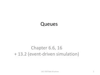
Event list as a linked list structure List of events scheduled to occur at time tq time signal new value ECE 545 – Introduction to VHDL
Event list as an array – Timing wheel List of events scheduled to occur at time tc time signal new value ECE 545 – Introduction to VHDL
Notation (i, vi’) – an entry of the event list associated with the time t indicating that at the time t the value of signal i is scheduled to be set to vi’ v(i) – current value at the output of gate i d(i) – nominal delay of gate i ECE 545 – Introduction to VHDL
Top-level algorithm while (event list not empty) begin t = next time in list process entries for time t end ECE 545 – Introduction to VHDL
Process entries for time t - Basic version Activated = Ø /* set of activated gates = empty set */ For every entry (i, vi’) pending at the current time t if vi’ ≠ v(i) then begin /* it is indeed an event */ v(i) = vi’ /* update value of signal i */ for every j on the fanout list of i begin update input values of j add j to Activated end end For every j Activated begin vj’ = evaluate(j) schedule (j, vj’) for time t+d(j) end ECE 545 – Introduction to VHDL
Event-driven simulation - example time 8 10 12 (z, 1) (z, 0) (z, 0) ECE 545 – Introduction to VHDL
Notation lsv(j) – last scheduled value of j lst(j) – last scheduled time of j = time of the last event scheduled for signal j ECE 545 – Introduction to VHDL
Process entries for time t – True events only version – Two-pass algorithm Activated = Ø /* set of activated gates = empty set */ For every entry (i, vi’) pending at the current time t if vi’ ≠ v(i) then begin /* it is indeed an event */ v(i) = vi’ /* update value of signal i */ for every j on the fanout list of i begin update input values of j add j to Activated end end For every j Activated begin vj’ = evaluate(j) if vj’ ≠ lsv(j) then begin schedule (j, vj’) for time t+d(j) lsv(j) = vj’ end end ECE 545 – Introduction to VHDL
Process entries for time t – True events only version – One-pass algorithm For every entry (i, vi’) pending at the current time t begin for every j on the fanout list of i begin update input values of j vj’ = evaluate(j) if vj’ ≠ lsv(j) then begin t’ = t + d(j) if t’ = lst(j) then cancel event (j, lsv(j)) at time t’ schedule (j, vj’) for time t’ lsv(j) = vj’ lst(j) = t’ end end end ECE 545 – Introduction to VHDL
Delta delay ECE 545 – Introduction to VHDL
Delta delay A propagation delay of 0 time units is equivalent to omitting the after clause and is called a delta delay. Used for functional simulation. ECE 545 – Introduction to VHDL
Two-dimensional aspect of time ECE 545 – Introduction to VHDL