Injection Moulding Technology - Part 3
1.84k likes | 3.32k Vues
Welcomes you to. Injection Moulding Technology - Part 3. Introduction. Safety. Telephones. Registration. Practical sessions. Smoking. Workshop access. Refreshments. Personal issues. Messages. Your contribution. Aim of course.

Injection Moulding Technology - Part 3
E N D
Presentation Transcript
Welcomes you to Injection Moulding Technology - Part 3
Introduction • Safety • Telephones • Registration • Practical sessions • Smoking • Workshop access • Refreshments • Personal issues • Messages • Your contribution
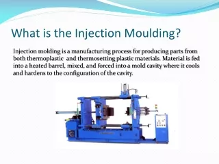
Aim of course To provide delegates with an in-depth knowledge of the injection moulding process, in order to competently and safely set up a range of moulding machines, to achieve product quality and output.
Testing Through out the course there will be; Lesson Assessments Class Exercises Evening Assessments In your manual section 1, PAGE 8
Knowledge Assessment Conducted at the end of the course, successful completion of which: • Awards a P.T.I.C Level 3 Polymer • Processing Certificate. • Will assist personnel working towards the • achievement of an Injection Moulding Diploma • certificate. • Allows progression onto practical element within • Injection Moulding Technology - Part 3, resulting • in the full award of a P.T.I.C Approved Technician.
Timetable DAY 1 09:00 ADMINISTRATION & INTRODUCTIONS 09:15 MACHINE CONSTRUCTION – CLAMP END 10:30 BREAK 10:45 MACHINE CONSTRUCTION - INJECTION END 12:30 LUNCH 13:00 SELF DEVELOPMENT (review morning session) 13:30 MACHINE CONTROL & INSTRUMENTATION 15:00 BREAK 15:15 MACHINE CONTROL & INSTRUMENTATION 16:00 HEALTH & SAFETY 16:45 FINISH (evening assessments and Quality)
Timetable DAY 2 09:00 QUALITY(review evening assessments) 10:30 BREAK 10:45 MACHINE PRACTICAL No 1 12:30 LUNCH 13:00 SELF DEVELOPMENT (review morning session) 13:30 MACHINE PRACTICAL No 1 15:15 BREAK 15:30 MACHINE PRACTICAL No 1 16:45 FINISH
Timetable DAY 3 09:00 REVIEW HOME WORK 09:15 MOULD TOOLS 10:30 BREAK 10:45 POLYMER MATERIALS 12:30 LUNCH 13:00 SELF DEVELOPMENT (review morning session) 13:30 PROCESS & TROUBLESHOOTING 15:15 BREAK 15:30 PROCESS & TROUBLESHOOTING 16:45 FINISH
Timetable DAY 4 09:00 HOME WORK REVIEW 09:30 MACHINE PRACTICAL No 2 10:30 BREAK 10:45 MACHINE PRACTICAL No 2 12:30 LUNCH 13:00 SELF DEVELOPMENT (revision of course) 13:30 MACHINE PRACTICAL No 2 14:30 BREAK 14:45 DELEGATE FEEDBACK 15:00 END OF COURSE ASSESSMENT 17:00 FINISH
Injection Moulding Technology Part 3 Machine Construction Clamping End
Session aim To provide an in-depth understanding of the clamp unit construction, operation and setting, including variations in terminology.
Session objectives By the end of the session you will be able to: • State the functions of the clamping unit. • Name design alternatives for the clamp unit. • Explain how to set and adjust the locking tonnage.
Terminology Whenever possible: Daylight = 2-3 x depth of moulding
Terminology Mould Height Moving Half Fixed Half
Clamping end – Component Parts Moving Platen Mould Clamping Cylinder Ejection Fixed Platen Tie Bar
Direct hydraulic lock Single Hydraulic Cylinder
Direct hydraulic lock Advantages 1. Self lubricating 2. Low maintenance 3. Larger tonnages 4. Tonnage set more accurately and easier to adjust Disadvantages 1. Slower movements 2. Larger pumps 3. Seals expensive to replace 4. Increased power requirements
High pressure applied 1.0mm
Spacer What if it doesn't reach ? Toggle locking mechanism
Hydraulic Driven Gear for Mould Height Adjustment Toggle Lock Machine
Toggle mechanism Advantages 1. Fast movements 2. Natural acceleration and deceleration 3. No forces on the clamping cylinder when locked. Disadvantages 1. High stress/strain 2. High maintenance 3. Links need lubrication 4. Usually smaller than 2200 Tonnes
Clamp tonnage estimation Calculate projected area: 4 x 3 = 12in2 Polycarbonate x 4 = 48T 12in2 3” 4” Rule of thumb = 2 - 4 tonnes/in2 480 KN
Clamp tonnage estimation Calculate projected area: 8cm x 7cm 56cm2 = POLYPROPYLENE 56cm2 x 0.3 = 16.8T 7cm 8cm Rule of thumb = 0.3 - 0.6 tonnes/cm2 168 KN
4 Tons per Sq Inch ABS PS POM PP PE PA PVC PC PMMA Clamp tonnage estimation To be used as a guide line only! CM = 0.6 Tonnes per Sq CM 0.4/0.5 0.3 INCHES = 3 2
Clamp end - 7 point plan • Zero parameters • Obtain movement • Set positions • Set speeds • Set ejectors • Set tonnage • Check mould safety
Injection Moulding Technology Part 3 Machine Construction Injection End
Session aim To provide an understanding of the construction, operation, setting up and terminology, relevant to the injection unit of the moulding machine.
Session objectives • Describe the basic construction of the injection unit. • Name three zones of a general purpose screw. • Describe the design of PVC and Nylon screws. • Identify the function of injection unit process • parameters. • List commonly used nozzle designs and describe • their application. • Explain the term “specific injection” pressure. At the end of this session you will be able to:
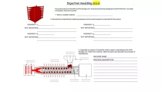
Reciprocating screw injection unit Feed Hopper Fixed Platen Reciprocating Screw Injection Cylinder Feed Throat Nozzle Drive Unit Barrel Heaters Barrel Check Valve Carriage Cylinder Carriage Complete the exercise in your course manual, Injection Unit Components.
Screw rotation What is back pressure? What is decompression?
General purpose screw Metering Compression Feed
Length to diameter ratio (LD ratio) Hopper Barrel Diameter 60mm Length 1200mm Length = 1200mm Diameter = 60mm L/D ratio = 1200/60 = 20:1
Compression ratio Volume in this flight = 1 Volume in this flight = 3 Compression ratio = 3:1
Nozzle & screw removal Heater Band End Cap Nozzle
Nozzle types Open • Shut-off
Spring loaded shut-off nozzles • Shut-off
Nozzle seating Nozzle with too large a hole Correctly sized nozzle Nozzle with too sharp a radius Nozzle with too shallow a radius
Hydraulic pressures Set Injection Pressure 90 bar Peak Pressure Holding Pressure 50% Speed Maximum Pressure Switchover Point 180 bar What is specific pressure? Actual Pressure Injection Phase Holding Phase
Specific Injection Pressure 35 140 16 2240 58 Screw Diameter = 45 mm (4.5 cm) Piston Diameter = 140 mm (14 cm) Hydraulic Pressure Specific Pressure 140 Bar 1358 Bar Intensification factor = Piston area = 153.9 sq. cm Screw area = 15.9 sq. cm = 9.7 Negri Bossi 100T Specific Inj.Pressure Shot Capacity Screw Diameter Hydraulic Pressure Intensification Factor = 45 140 9.7 1358 72 X Screw area = 15.9 sq. cm Piston area = 153.9 sq. cm
Hydraulic pressure - Specific injection pressure Typical 360 ton moulding machine Specific pressure (in front off the screw) bar psi 2100 2055 1800 25000 1510 1500 20000 70 dia (2.76 in.screw) 1200 1155 15000 60 dia (2.36in.screw) 80 dia (3.15 in.screw) 10000 600 5000 300 0 30 60 90 120 150 bar Reading at pressure gauge
Mould cavity specific pressure Flow path length = 200 mm Wall thickness = 1.5 mm 500 bar Specific pressure Material to be used is PVC
Projected area VS. clamp force Mould projected area = 600 Sq.cm Specific pressure was = 500 bar 300 tonne 3000 KN Use the charts provided in your course manual to complete the clamping force requirements.
Projected area 750 bar Specific pressure
Mould area VS. clamp force 90 tonne 900KN