Download
1 / 25
260 likes | 507 Vues
Medipix3 Irradiation Studies. Irradiation Studies of a 130nm Large Area Pixel Chip Richard Plackett – CERN Medipix Group TWEPP 2009, Paris, 22 nd September. Overview. Introducing the Medipix3 Chip Updates from Medipix2 Charge Summation Spectroscopic mode Example Application

E N D
Medipix3 Irradiation Studies Irradiation Studies of a 130nm Large Area Pixel Chip Richard Plackett – CERN Medipix Group TWEPP 2009, Paris, 22nd September
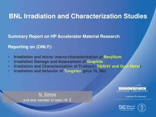
Overview Introducing the Medipix3 Chip Updates from Medipix2 Charge Summation Spectroscopic mode Example Application Brief Radiation Damage Overview Specific Design Issues Irradiation Measurements up to 460Mrad Threshold, Noise and Gain Results DAC Stability Irradiation Measurements up to 3Mrad Additional Run in the Worst Case The Medipix3 Design team is Xavier Llopart, Rafael Ballabriga &Winnie Wong These Measurements taken and analysed by myself, Xavier Llopart & Rafael Ballabriga Thanks to them and all the CERN group for their support Introduction to Medipix3 Radiation Damage Design Issues 460MRad Irradiation 3MRad Irradiation
Hybrid Pixel Detectors Ionizing Particle A hit in the sensor deposits charge Introduction to Medipix3 sensor h+ Radiation Damage The charge passes to the analogue amplifiers e- Design Issues The Medipix 3 charge summing circuit operates 460MRad Irradiation Analogue amplification Positive or negative sensor bias 3MRad Irradiation Digital processing The counter is iterated and read out with the shutter 10001110101 Chip read-out Medipix3 adds communication between the pixel analogue electronics
Imaging by Photon Counting • Application of HEP idea to x-ray detection and medical imaging, the concept behind Medipix chips. • Photon counting devices provide superior contrast and dynamic range to charge integrating devices. • Counting only hits that pass threshold rejects noise in the sensor giving clearer images. • Dynamic range is limited only by front end response and depth of in-pixel counters. Introduction to Medipix3 Radiation Damage Design Issues 460MRad Irradiation 3MRad Irradiation
Medipix 3 • Medipix3 builds on the success of Medipix2 as a single photon counting imaging chip • Added Features • Analogue charge summing to keep all charge information • Spectroscopic mode with 8 threshold levels • Continuous readout mode (no dead time) • Increased counter depth increasing dynamic range • Increased readout speed • Increased radiation hardness from 130nm CMOS process Introduction to Medipix3 Radiation Damage Design Issues 460MRad Irradiation 3MRad Irradiation
Status • First engineering run (12 wafers of 100 chips) delivered early this year • Wafer probing complete (from 11 wafers – 437 Class A + 166 ClassB) • Initial readout system working at low speed • Initial characterisation underway • One wafer diced and bonded to PCBs • First bump bonded assemblies with wafers expected soon • Initial radiation hardness measurements underway Introduction to Medipix3 Radiation Damage Design Issues 460MRad Irradiation 3MRad Irradiation
Charge Summing Medipix3 can be set to sum charge across four pixel clusters to prevent hits being lost due to charge sharing A hit in the sensor deposits charge across four pixels Introduction to Medipix3 Radiation Damage The analogue comparators assign the charge to the pixel with the most hits Design Issues 460MRad Irradiation This prevents ‘lost’ charge by partial hits not passing threshold 3MRad Irradiation 10001110101 The threshold is applied to the summed charge and read out when the shutter closes
Spectroscopic Mode • By connecting 4 pixels into a larger super pixel, eight threshold levels are available to us in the digital part of the pixel… Introduction to Medipix3 Amplifier response Radiation Damage Counter 1 Counter 2 Design Issues Counter 3 Counter 4 Counter 5 460MRad Irradiation Counter 6 Counter 7 3MRad Irradiation Counter 8 • Each threshold is adjustable, allowing a wide range of settings. • This gives us enough flexibility to capture reasonable spectra in many different applications
MARS Computed Tomography System Introduction to Medipix3 Radiation Damage Design Issues 460MRad Irradiation 3MRad Irradiation
Radiation Damage • 130nm is expected to be significantly more radiation hard than 250nm CMOS because of the much thinner gate oxides • Radiation damage occurs because the regular crystal structure of a device is disturbed. This causes a number of effects among which are: • Change of effective doping concentration (esp. in diodes) • Increase leakage current (esp. in detectors) • Charge trapping (esp. in detectors) • Oxide charging (esp. in CMOS) • Single Event Upset (in logic circuits) • Photons and hadrons cause different types of damage, point and cluster respectively. Introduction to Medipix3 Radiation Damage Design Issues 460MRad Irradiation 3MRad Irradiation
Analogue Switch Problem One of the DAC outputs is particularly sensitive due to a minor design oversight The current drawn by some minimum sized NMOS transistors when the matrix is irradiated can overload the DAC output stage stopping the pixel front end from functioning under nominal bias conditions Here it happened at less than 1MRad so we were able to take no proper front end measurements during the 400MRad irradiation Introduction to Medipix3 Radiation Damage Design Issues 460MRad Irradiation 3MRad Irradiation
Solution • The chip operation can be recovered by modifying the DAC settings. • In particular the pre-amp reference voltage was reduced modifying the front-end operating point. • Next wafer production fix Cas DAC issue by eliminating the (unneeded) leaky NMOS Introduction to Medipix3 Radiation Damage Design Issues 460MRad Irradiation 3MRad Irradiation
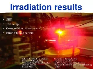
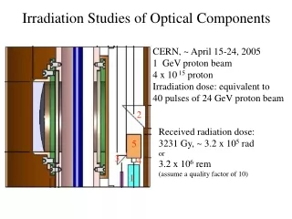
400Mrad Irradiation Used a calibrated X-ray machine (Seifert RP149) Beam profile is smaller than the Medipix3 → Two runs: Introduction to Medipix3 On the Pixel Matrix 60Mrad Threshold Variation Gain Variation Noise Increase Radiation Damage Design Issues 60 MRad 460MRad Irradiation On the Periphery 400Mrad Check DACs E-fuses Logic functionality 3MRad Irradiation 460 MRad 400 MRad
Performance after 460MRad Threshold Noise Introduction to Medipix3 Radiation Damage Yield artifact Design Issues 460MRad Irradiation 3MRad Irradiation σ=1.72 ke- µ=9.3 ke- σ=12.9 e- µ=71.6 e- Threshold can be re-tuned using 5 bit equalisation
Performance after 460MRad Introduction to Medipix3 Radiation Damage Row[0:255] Yield artifact Design Issues 460MRad Irradiation 3MRad Irradiation Qin=2ke- After 460MRad there is essentially no gain variation observed
DAC Measurement PMOS DAC Band Gap NMOS DAC (Preamp) Accumulated dose of 396 Mrad Accumulated dose of 396 Mrad Accumulated dose of 396 Mrad 33mV 9mV Introduction to Medipix3 Radiation Damage Design Issues 460MRad Irradiation 3MRad Irradiation
3MRad irradiation Worst effect at 3MRad, After this the effect of further radiation is much less. Irradiated a small area of the chip up to 3Mrad to try and keep Cas DAC working by only damaging a limited number of pixels Introduction to Medipix3 3 MRad Radiation Damage Design Issues The main effect observed is the shift in the threshold and amplifier response caused by the DAC moving… The front end leaves its normal operating point at nominal bias conditions at 1500krad, although it remains possible to read out the chip up to 3Mrad. The front end can be recovered by increasing the value of the IKRUM DAC. 460MRad Irradiation 3MRad Irradiation
3MRad Noise and Gain Result Introduction to Medipix3 Radiation Damage Row[0:255] Yield artifact Design Issues 460MRad Irradiation 3MRad Irradiation In this worst case situation the noise is still less than 100e- and the gain variation is still minimal Qin=2ke-
Next Steps • Repeat 400MRad measurement with bare chips and full sensors, recovering performance at each point to take measurements. • Begin hadronic measurements rather than x-rays, possibly in collaboration with LHCb upgrade projects. • Measurements with different sensors eg 3D or diamond • Next wafer production to fix Cas DAC issue by eliminating the (unneeded) leaky NMOS Introduction to Medipix3 Radiation Damage Design Issues 460MRad Irradiation 3MRad Irradiation
Conclusions • Medipix3 has been operated successfully after an exposure to a very large x-ray dose. • This is very encouraging for readout chips in SLHC trackers and other high radiation environments. • Confirmation in a full chip that 130nm is intrinsically more radiation tolerant than 250nm. • You still need to bear radiation damage in mind when designing chips to avoid unexpected problems. • Thank you for your attention. Introduction to Medipix3 Radiation Damage Design Issues 460MRad Irradiation 3MRad Irradiation
Backup Slides • This page has been left intentionally blank
460MRad Threshold variation Row[0:255] After annealing we see ~20 THL DAC steps variation (<1ke-) between areas non irradiated and areas irradiated at 60, 400 and 460 Mrad. This variation can be corrected by the threshold equalization procedure (5 bits)
General behavior after 3 Mrad Threshold Noise Yield artifact
THL Shift at 3MRad Row[0:255] Main contributor is the protection diode. In order to minimize the pixel to pixel threshold variation Ikrum is set to 16nA which indicated that the leakage of this diode at 3Mrad is ~5 to 10 nA. This is the worst radiation operation point.
Difference in CAS DAC range Good chip (F7) shows CAS DAC dynamic ranger larger than other chips → Less ids transistor leakage in analog switches?