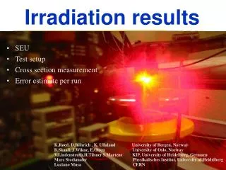
Irradiation results
Irradiation results. Radiation effects Test setup Cross section measurement TPC Readout Controller Unit TPC radiation tolerance scheme TRD/TPC DCS PHOS FEE. K.Røed, D.Röhrich , K. Ullaland, B. Pommeresche University of Bergen, Norway

Irradiation results
E N D
Presentation Transcript
Irradiation results • Radiation effects • Test setup • Cross section measurement • TPC Readout Controller Unit • TPC radiation tolerance scheme • TRD/TPC DCS • PHOS FEE K.Røed, D.Röhrich , K. Ullaland, B. Pommeresche University of Bergen, Norway B.Skaali, J.Wikne, E.Olsen University of Oslo, Norway V.Lindenstruth, H.Tilsner, S.Martens, D. Gottschalk KIP, University of Heidelberg, Germany U. Kebschull, G. Tröger KIP, University of Heidelberg, Germany M. Stockmaier Physikalisches Institut, University of Heidelberg L.Musa, H. Müller CERN
1. Radiation effects K.Røed, D.Röhrich , K. Ullaland, B. Pommeresche University of Bergen, Norway B.Skaali, J.Wikne, E.Olsen University of Oslo, Norway V.Lindenstruth, H.Tilsner, S.Martens, D. Gottschalk KIP, University of Heidelberg, Germany U. Kebschull, G. Tröger KIP, University of Heidelberg, Germany M. Stockmaier Physikalisches Institut, University of Heidelberg L.Musa, H. Müller CERN
Radiation effects in semiconductors • Single Event Effects (SEE) • Stochastic process • E.g. soft errors (upsets) in SRAM FPGA • Measurement: cross section (per bit, per device) [cm2] for bit-flip under irradiation • Radiation damage • Cumulative effect • Deterioration of performance, sometimes threshold behaviour • Measurement: performance as function of fluence or dose • Dose of 63 MeV protons at a fluence of 1011 protons/cm2/s in silicon semiconductors: 140 Gy = 14 krad • Dose of 25 MeV protons at a fluence of 1011 protons/cm2/s in silicon semiconductors: 280 Gy = 28 krad
Single Event Upset (SEU) • High-energetic hadrons induce nuclear reactions in the silicon (E > 20 MeV - protons, neutrons, pions, kaons) • Intermediate energy neutrons (2 MeV < E < 20 MeV) contribute little (10%) to SEUs • (Almost) no effect due to thermal neutrons • Heavy recoil ions from reactions ionize the material • Charge deposition leads to a change in state of a transistor (SEU) • Soft error – can be corrected (rewriting or reprogramming) p • Si(p,2p)Al • Si(p,p)Mg • Si(n,p)Al • Si(n,)Mg Si
Upset detection in FPGAs • SEU • Upset in configuration SRAM • Measured by reading back configuration bitstream • SEFI • Single Event Functional Interrupt • Upset in design • Ratio SEU/SEFI 4 – 10 • Routing: 90% of resources • Application: 90-98% of config cells are not used
Serial Slow Control Network SCSN Serial Slow Control Network SCSN Upset detection in ALTERA FPGAs • Two types of concern • Upsets in configuration SRAM cells • Single bitflips in register elements • The APEX20K400E offers no direct readout of configuration SRAM • Indirectly detection of configuration upset through the VHDL design • Error observed reflects a change in logic due to a configuration upset, and not the configuration upset itself • A fixed pattern is shifted through and compared for setups when read out Data out Data in FPGA 0000000 1000000 0100000 0010000 0001000 0000100 0000010 0010001 0000000 0000000 . . . 0000000 0000000 1000000 0100000 0010000 0001000 0000100 0000010 0000001 0000000 0000000 . . . 0000000
Example of analyzing data Shiftregister in logic elements FIFO in internal RAM Configuration upset Single upset
Test setup (1) • Oslo Cyclotron • 25 and 28 MeV external proton beam • flux ~ 107 – 108 protons/s cm² • Flux measurements: Uranium fission target + TFBC • Intensity monitor: faraday cup • Beam profile: spot 1.5cm x 1.5cm
Test setup (2) • TSL (Uppsala) • Proton beam • 38 and 180 MeV external proton beam • flux ~ 107 – 108 protons/s cm² • flux measurements: Uranium fission target + TFBC • intensity monitor: scattered protons -> scintillator • beam profile: 3cm • Neutron beam • large beam spot
Results (1) • APEX20k400 • SEFI - shift register design K. Røed, Master thesis, UiB, 2004
Results (2) • APEX20k400 • Energy dependence of cross section • CS = 6.0 x 10⁻⁹ 1.1 x 10⁻⁹ cm2 (E >30 MeV)
Results (3) • Energy dependence of cross section - comparison to simulations
Results (4) • ALTERA EPXA1F484C1 - ARM See S. Martens, Diploma thesis, KIP (2003)
Cross section results – summary (1) • SEFI CS for Altera devices
Cross section results – summary (2) • SEFI and SEU CS for Xilinx devices
Cross section results – summary (3) • SEU CS per bit for Xilinx technologies
Radiation levels – simulation (1) Georgios Tsiledakis, GSI
Radiation levels – simulation (2) Georgios Tsiledakis, GSI
Radiation levels – simulation (3) Georgios Tsiledakis, GSI
Radiation levels – simulation (4) • Comparison to ALICE-INT-2002-28 • Difference in flux of factor 2 • 790 Hz (averaged of all z) vs 384 Hz (absorber side, worst case)
Error estimates per run • SEUs in RCU main FPGA • Errors per run (4 hours)
Conclusion (1) • SRAM based FPGAs • Error rate is so low that one can cope with it – if SEUs can be detected instantenously or FPGA can be reconfigured in real-time • ALTERA FPGAs do not provide real-time readback of configuration data nor disclose format of bitstream • Better choice: XILINX Virtex-IIPro FPGAs • Real-time (= while running) readback of configuration data for verification • Partial reconfiguration while running • Existing infrastructure, running under linux (e.g. on DCS board), allowing full and high level control of the FPGA internals while running • Radiation tolerant scheme: see next chapter
Conclusion (2) • Fallback solution: FLASH based FPGA (Actel) • ProASICPlus FLASH Family FPGAs • Preliminary irradidation results • Device: APA075 • Test method: reading back configuration • Failure (probably latch-up) after a fluence of 3.7x 10¹¹ protons/cm2 dose of 1000 Gy • Expected dose in 10 years of ALICE: ~ 5.7 Gy
Next steps • Develop radiation tolerance strategy (see chapter 8) • Decide to migrate RCU-FPGA to XILINX • Select appropriate device w.r.t. resources (e.g. number of I/O cells) • Decide to keep DCS board unchanged • Keep Actel-FPGA as fallback solution • Port RCU design to new develop environment • Port existing reconfiguration scheme to DCS board • Verify expected performance under irradiation • XILINX test @ OCL in August • System test @ TSL in fall with large beam spot ( 30cm)
Radiation test of RCU components (2) • Example: GTL bus transceiver 10 y ALICE 10 y ALICE
Radiation test of RCU components (3) • Summary 10 y ALICE
5. Radiation tolerance scheme V.Lindenstruth, U. Kebschull, G. Tröger KIP UiB, UiO
FPGAs: Active Reconfiguration for Radiation Tolerance Gerd Tröger Technische Informatik Universität Leipzig +49-341-97-32218 gerd@ti-leipzig.de troeger@informatik.uni-leizpig.de
Active Partial Reconfiguration • Most commonly: full configuration only, device reset • Active Partial Reconfiguration: ca. 6-8 years, since Virtex series, uninterrupted operation • Configuration Space divided into units, “frames” in Xilinx terminology • ‘Partial’: frames are individually reconfigurable • ‘Active’: without interrupting the device, glitch-free: no change → no signal flanks • Configuration is ‘atomic operation’ (no bit shifting)
Radiation Tolerance • FPGAs: configuration plane = big memory → particularly radiation sensitive • Normal Approach (ASICs): Hamming Codes for registers, TMR (triple module redundancy) for critical components • Not practical for the configuration plane: too expensive for normal COTS FPGAs • → Upset Mitigation by Refresh • → Active Partial Reconfiguration feature used to continuously ‘repair’ the FPGA configuration • Alternative: special FPGAs ($$$)
Preliminary Test Results • SEFI test with Xilinx Virtex-II Pro FPGA • reconfiguration started after 200 seconds: • errors are corrected continuously
Preliminary Conclusions • Test conditions • Flux = 3.7 x 10¹¹ protons/cm2/s • Reconfiguration time = 5 s • Real life • Flux = 7.9 x 10² hadrons/cm2/s • Reconfiguration time = 10 ms • Duty cycle: 1011 times better in real life
Target System Implementation (1) • FPGA on RCU board • External SelectMAP configuration interface (8 bit parallel, 50/66 MHz); alternatively JTAG (~5 MBit/s) • Rad-Hard controller + memory for reconfiguration • Alternatively: non rad-hard controller, ‘best effort’ strategy • expected individual upset rates (1 per 400 hours) and downtime (approx. ~ controller reboot time: 10 sek.) are low enough to justify this approach
fpga/ phys.resource/ app.core/ platform/ config region1/ region2/ mycore.bit R1 mycore.sym R3 R4 R2 Target System Implementation (2) • FPGA on RCU • Reconfigured via RCU bus • DCS FPGA running Linux provides tool • ICAP: “Internal Configuration Access Port” • internal equivalent of the SelectMAP interface • Linux driver • FPGA virtual file system
6. TRD DCS board K.Røed, D.Röhrich , K. Ullaland, B. Pommeresche University of Bergen, Norway B.Skaali, J.Wikne, E.Olsen University of Oslo, Norway V.Lindenstruth, H.Tilsner, S.Martens, D. Gottschalk KIP, University of Heidelberg, Germany U. Kebschull, G. Tröger KIP, University of Heidelberg, Germany M. Stockmaier Physikalisches Institut, University of Heidelberg L.Musa, H. Müller CERN
DCS BoardProduction Readiness Review January 2004 Project Link : http://www.kip.uni-heidelberg.de/ti/DCS-Board/current/ page 42 Board Version 1.16Sept./ Oct. 2003 Dirk Gottschalk Holger Höbbel Volker Kiworra Tobias Krawutschke Volker Lindenstruth Stefan Martens Vojtech Petracek Marc R. Stockmeier Heinz Tilsner Chair of Computer Science and Engineering / Prof. Dr. Volker Lindenstruth / http://www.kip.uni-heidelberg.de/ti/
DCS Board Production Readiness Review Page 43 DCS board schematicoverview.
Total Dose in 10 ALICE years (ALICE-INT-2002-28) • TPC: 16 Gy 5 x 10⁹ protons/cm2 @ 25 MeV 15 sec @ 50 pA 0.1 sec @ 1 nA • TRD: 1.8 Gy 5 x 10⁸ protons/cm2 @ 25 MeV
DCS Board Production Readiness Review Radiation Beamtest Results (1) : Page 45 *1) D. Gottschalk/KIP, S. Martens/KIP, M. Stockmeier/PI, P. Struck/KIP, H. Tilsner/KIP at University of OSLO November 2003*2) L. Musa / CERN made rad tests as well at CERN and University of OSLO.*3) Links provide documents for details.
DCS Board Production Readiness Review Radiation Beamtest Results (2) : Page 46 *1) D. Gottschalk/KIP, S. Martens/KIP, M. Stockmeier/PI, P. Struck/KIP, H. Tilsner/KIP at University of OSLO November 2003*2) L. Musa / CERN made rad tests at CERN and University of OSLO.*3) Links provide documents for details.
DCS Board Production Readiness Review Radiation Beamtest Plots : Page 48 First error after 146 x 10 ALICE years 1nA Beam current Test plots by Stephan Martens Diploma Thesis 2003 Flash EPROM Beam Test Plot
DCS Board Production Readiness Review Radiation Beamtest Plots : Voltage regulators MIC29301 Page 51 * => 55 x 10 ALICE years Tests by M. Stockmeier and D. Gottschalk
DCS Board Production Readiness Review Radiation Beamtest Plots : Voltage regulator LP3962 Page 52 * => 107 x10 ALICE years Tests by M. Stockmeier and D. Gottschalk
DCS Board Production Readiness Review Radiation Beamtest Plots : LP3962 recovery over night Page 53 60000 samples => 11 hours Tests by M. Stockmeier and D. Gottschalk