Download
1 / 63
630 likes | 801 Vues
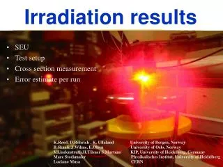
Some Irradiation Results from a Chip in UMC018 Technology. Peter Fischer for Christian Kreidl Heidelberg University. Summary. UMC018 Chip was irradiated with X-rays to 7.5Mrad No degradation after annealing Strange effects around 1.2Mrad Work done in the frame of the DEPFET project

E N D
Some Irradiation Results from a Chipin UMC018 Technology Peter Fischer for Christian Kreidl Heidelberg University P. Fischer, ziti, Heidelberg
Summary • UMC018 Chip was irradiated with X-rays to 7.5Mrad • No degradation after annealing • Strange effects around 1.2Mrad • Work done in the frame of the DEPFET project • Measurements by Christian Kreidl • Chip by Ivan Peric P. Fischer, ziti, Heidelberg
The Chip • DCD1 = DEPFET Current Digitizer • Readout Chip for DEPFET Sensor columns DEPFET Sensor goes here… DCD1 Chip current memory cells to subtract pedestal 8 bit ADCs using current memory cells P. Fischer, ziti, Heidelberg
More Details... Test Injection current Regulated Cascode Sampling Current Subtract 2 ADCs ADC Output Logic Generate ADC + memory cell control signals ADC result calculation, MUX per pixel 3 x 6 lines ADC Steering Signals Serializer Sample Monitoring Pad Clock Divider 600MHz sync for FPGA, Switcher P. Fischer, ziti, Heidelberg
Chip Layout & Design • UMC 0.18µm technology, 2 x MiniASIC size • ADC in radhard layout (enclosed NMOS, guard rings) • Digital part without any precautions • 72 inputs P. Fischer, ziti, Heidelberg
Pixel Layout Size x: 180µm Size y: 110µm regulated cascode two 8 bit algorithmic current mode ADCs working interleaved digital stuff (conservative layout) bump pad with 60µm opening test injection P. Fischer, ziti, Heidelberg
Chip Test Setup • Chip glued & bonded to PCB – no cover • Readout via USB P. Fischer, ziti, Heidelberg
Irradiation Facility in Karlsruhe • 60 keV X-Ray tube at Institut für Nuclear Physics, Karlsruhe • 100-250 krad/h (depending on distance), calibrated setup • Thanks to Dr. Simonis, Mr. Dierlamm and Mr. Ritter for help! P. Fischer, ziti, Heidelberg
Irradiation • Dose: • 31h @99.5 krad/h (d=180mm) = 3.1 Mrad • 18h @241 krad/h (d=100mm) = 4.4 Mrad • Total = 7.5 Mrad • DCD Operation Mode • clock running permanently • control registers loaded every 30s with default values(precaution against SEU) • Measurements (while tube is on!): • current consumption on VDD (= analog + digital) • on selected pixels:- Current memory cell operating range- ADC characteristics- Test injection current value P. Fischer, ziti, Heidelberg
Current consumption • Total supply current (analog + digital) • Current rises until 1.2Mrad, then settles to pre-rad value 1.2Mrad = pre-rad Probably bit flip In Bias DACs P. Fischer, ziti, Heidelberg
Current Memory Cells • Cell keeps input voltage constant within ± 10µA P. Fischer, ziti, Heidelberg
ADC Characteristic (ADC value vs. Injection DAC) • Test current injected via ON-CHIP injection DAC • SEUs during measurement (more at 1.2Mrad !) • most effects @<1.2Mrad, some ADCs BROKEN • after 7Mrad and 6 days annealing: back to pre-rad behavior Pixel 59 Pixel 71 BROKEN @ 1.2Mrad 0 Mrad = after anneal. 7 Mrad Many SEUs P. Fischer, ziti, Heidelberg
Test Injection Current vs. DAC value • Test injection current is ok (not dead). Some variation. P. Fischer, ziti, Heidelberg
ADC Histograms • Plot deviation from straight line • 45nA (@0) 70nA (@1.2-7 Mrad) 44nA (7 day anneal) P. Fischer, ziti, Heidelberg
ADC noise map • All ADCs back to initial values after anneal Readout problems due to setup Readout problems due to setup P. Fischer, ziti, Heidelberg
Summary • No degradation after 7Mrad of 60keV X-rays • Strange effects at 1.2 Mrad (power higher, ADC dead) P. Fischer, ziti, Heidelberg
Thank you! P. Fischer, ziti, Heidelberg
Bump Bonding Status in HD Peter Fischer, ziti, Uni Heidelberg for Christian Kreidl P. Fischer, ziti, Heidelberg
Reminder • We do gold stud bumping: • Create a gold sphere on bonder • Place ball on chip, Thermocompress, rip off wire • Place all bumps • Flip & press & heat (~50g / bump) • Can put bumps on both sides to reduce forces • Can put isotropic glue with conducting particles • Key parameters: • Diameter of balls ~ 45µm • Min. bond pad size ~ 60µm • Min pitch ~ 100µm • Advantages: • single chip (prototype) process, in house, cheap • Drawbacks: • sequential, limited # of pads, large force, possible destruction of electronics under pad, need hard substrate, no rework P. Fischer, ziti, Heidelberg
Tests with Dummy Chips • Aluminum on Silicon structures • Substrate and ‘chip’ • Trace pattern to check contact & shorts SuS@Uni-Heidelberg P. Fischer, ziti, Heidelberg
Chip with Bumps P. Fischer, ziti, Heidelberg
Flipped Assemblies • 80g/bump: all bumps connected, no shorts • 20g/bump: 4 of 6 snakes connected, chip fell off SuS@Uni-Heidelberg P. Fischer, ziti, Heidelberg
Large Size Module • Mechanical demonstrator of ILC vertex detector module • no electrical tests • check how to handle a large silicon device • check how low pitch flipping works • 16 DCD (dummy) chips • 36 Switcher (dummy) chips • 11,9 cm x 1,6 cm • No electrical test possibilities 8 ‘DCD’ chips 8 ‘DCD’ chips 2 x 18 ‘Switcher’ chips P. Fischer, ziti, Heidelberg
Placing Chips Close to Each Other (side view) • Switcher (dummy) chips • 164 bumps each1 • ,4mm x 5,8mm • 60g/bump = 9,8kg/chip Edge of flip tool SuS@Uni-Heidelberg SuS@Uni-Heidelberg P. Fischer, ziti, Heidelberg
ILC Mechanical Sample SuS@Uni-Heidelberg P. Fischer, ziti, Heidelberg
Minimum gap 50µm gap 50µm gap SuS@Uni-Heidelberg P. Fischer, ziti, Heidelberg
Module End • 224 bumps/chip, 1.35mm x 4.95mm, 13.4kg/chip 200µm gap SuS@Uni-Heidelberg P. Fischer, ziti, Heidelberg
Full sample • One module populated with 52 chips • No failures ! SuS@Uni-Heidelberg P. Fischer, ziti, Heidelberg
Effort • Bonding process: cleaning, mounting, aligning, bumping • Switcher: 11min • DCD: 13min • Flipping process: pickup, aligning, thermocompression • 9 min • 2 days of work including learning • Improvements: • build better mounting device for single chip bumping (mechanical clamp) P. Fischer, ziti, Heidelberg
Thank you! P. Fischer, ziti, Heidelberg
ADC Design in Heidelberg Peter Fischer, ziti, Uni Heidelberg ADC Design: Ivan Peric P. Fischer, ziti, Heidelberg
Content • Algorithmic / Pipeline ADC principles • Voltage vs. Current Mode • ADC in DEPFET readout chip • Reminder: ADC of David Muthers (Kaiserslautern) • Comparison of figures of Merit P. Fischer, ziti, Heidelberg
Algorithmic (Cyclic) ADC • Idea: • Compare signal to half scale generate BIT • If BIT = 1: subtract half scale • Multiply result by two • Restart over again • Every cycle produces a new bit • Very popular architecture • Resolution limited by precision of Compare / Subtract / Multiply • Comparator requirements are relaxed by two threshold per stage (and some error correction) P. Fischer, ziti, Heidelberg
ADC Stage ADC DAC + + - k Bit P. Fischer, ziti, Heidelberg
Pipeline ADC 2 2 2 2 • Shift value through many stages • Can process one new value per cycle • More hardware • Faster • Can scale cells for lower precision in later cells Stage 1 Stage 2 Stage m-1 Stage m Vin Bit Alignment + RSD Correction P. Fischer, ziti, Heidelberg
Voltage vs. Current • Signal can be voltage or current • Voltage: • Often natural quantity delivered by circuit • Comparison simple • Add / Subtract & duplication with switched capacitor circuits • Large swings • Needs linear capacitors • Current • May require U->I conversion • Low swing operation • Add / Subtract very simple • Duplication with multiple current copy & add • Can do with simple, small capacitors • No obvious winner P. Fischer, ziti, Heidelberg
Standard Current Memory Cell • Tracking phase: Diode connected transistor • Sample on gate capacitance • Drawbacks: • Charge injection is signal dependent • Low output resistance & current dependent • Input potential current dependent • Large storage cap (low leak) decreases speed Iin / Iout P. Fischer, ziti, Heidelberg
Pixel Layout Two 8 Bit ADCs: Current memory cells, Comparators, Reference sources. Optimized, rad hard layout ADC timing signals (can be shared) 110µm 2 x Output Logic(shift registers…) Very conservative layout Using standard cells P. Fischer, ziti, Heidelberg
ADC Characteristic • 8 Bit ADC output vs. injection DAC value P. Fischer, ziti, Heidelberg
ADC Noise / INL • Plot deviation from ideal value for various inputs • Width mostly from noise in input stage P. Fischer, ziti, Heidelberg
Pipeline ADC (Design Study) P. Fischer, ziti, Heidelberg
Comparison: ADC from D. Muthers, Kaiserslautern • Voltage mode • Cyclic & Pipeline version • Early version used in TRAP chip P. Fischer, ziti, Heidelberg
Comparison • FoM = P / 2ENoB / f * 1012 (small is good) • ADC from HD are VERY small P. Fischer, ziti, Heidelberg
Thank you! P. Fischer, ziti, Heidelberg
Simple Serial Data Driver Peter Fischer, ziti, Uni Heidelberg P. Fischer, ziti, Heidelberg
Goal • Study a serial driver suited to directly drive an FPGA • Find out how • Complex • Large • Power hungry it is. • Later: study copper transmission: • how long can we go ? • How fast can we go ? • For which type of cable ? • for which power requirement ? P. Fischer, ziti, Heidelberg
Design choices • Use (free) Aurora protocol from Xilinx • No back channel • No channel bonding • Minimize protocol engine • Use radiation hard library for a test P. Fischer, ziti, Heidelberg
Aurora – Protocol • Physical layer interface – electrical levels, clock encoding, symbol coding • Channel initialization and error handling • Link layer: • Beginning / End of data • IDLE • Clock compensation • 8B/10B encoding • Arbitrary data format, Data packets with arbitrary length • 4 Phases: • Initialization • Synchronization of receiver clock (send some syncs) • Data transmission • Idle • Must inject clock compensation characters from time to time P. Fischer, ziti, Heidelberg
FIFO: (data buffer) Control FSM 8b/10b Encoder Serializer LVDS-Driver Components P. Fischer, ziti, Heidelberg
Initialisation RESET TXRES_0 ln_cnt < N+2 TXRES_1 zur Validierung res_cnt < 3 P. Fischer, ziti, Heidelberg