Download
1 / 20
200 likes | 405 Vues
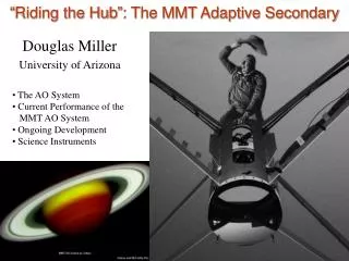
“Riding the Hub”: The MMT Adaptive Secondary. The AO System Current Performance of the MMT AO System Ongoing Development Science Instruments. Douglas Miller University of Arizona. The MMT AO NGS Team. Thomas Stalcup AO Scientist. Doug Miller Manager. Guido Brusa

E N D
“Riding the Hub”: The MMT Adaptive Secondary • The AO System • Current Performance of the MMT AO System • Ongoing Development • Science Instruments Douglas Miller University of Arizona
The MMT AO NGS Team Thomas Stalcup AO Scientist Doug Miller Manager Guido Brusa Mirror Scientist Vidhya Vaitheeswaran Software Engineer Phil Hinz PI Manny Montoya Technician Richard Sosa Technician Matt Kenworthy Instrument Scientist Searching for Exrasolar Systems
Advantages of a Deformable Secondary • IR observations are often limited by background light from the telescope optics. • Typical AO systems have background emission of ~20% • A deformable secondary system can have an emissivity of ~5-7%. • This can translate into 3-4x speed improvement in observations.
Thermally Clean Pupil Camera with cold pupil stop misaligned. Camera with cold pupil stop aligned. Blackbody emission From central hole in primary Images taken at 11 microns of the MMT adaptive secondary. Emissivity of the telescope was measured at 7%. Emission from sky Emission from sky and telescope
AdaptiveSecondaryMirror The MMT AO System Send new position commands to the 336 actuators Measure aberrationsdue to the atmospherewith WFS Camera Calculate secondaryshape needed to correctmeasured aberration Apply shape to thedeformable secondary Correct 56 modes WFS Camera Reconstructor Computer Loop runat 550 Hz 12x12 Shack-Hartmann Sensor
Current Performance • We typically achieve 20-30% Strehl in H band on bright stars, measured with an engineering camera installed in the AO top box. • Limiting magnitude is V~14.5 Curves are loop speeds of 550, 275, 137 and 68 Hz
Performance -vs- Mode Expected Strehl • Above 60 modes we do not see improved Strehl • Need an improved interaction matrix • “Reconstructor on the sky” technique currently being developed (Brusa et al. Glasgow SPIE 2004)
2002 2003 2004 2005 2006 • First light obtained November 2002 • Science observations interspersed starting in Jan. 2003. • Runs were scheduled once per trimester through 2004. • Two runs per trimester since January 2005. Current Rate: 50-100 nights/year
Ongoing Development • Transition of AO System to Facility Instrument • Calibration Stand • PC-based Reconstructor Computer • Rayleigh Laser Guide Stars (Stalcup, Baranec and Lloyd-Hart talks later today)
Facility Instrument • MMT staff will perform normal NGS AO operation • Installation of DM and NGS topbox • Operation of AO system for observers • Routine system maintenance • Software maintenance • Transition complete by early 2007 (hopefully) • AO Team will continue development and improvements
PC Reconstructor Computer • Current Reconstructor is a VME system written in Assembler (1990s technology) • Replacement is a dual processor PC-based system written in C under standard Linux. • Latencies of ~200 usec are achievable with straightforward implementation. Much more flexible. • Lab tests are complete. On-Sky test will take place Sunday night.
PC Reconstructor Computer • Speed up AO loop (~1 kHz) • Input accelerometer information into the AO loop to compensate for the 20 Hz vibration • Chop with AO secondary • Test new algorithms
Spherical Calibration Mirror Deformable Mirror Calibration Stand • The DM is convex! • Test stand uses a Hindle optical test to measure the surface shape of the DM • All lenses in the test stand are spherical • Allow us to calibrate the flat position • The current gap(40 microns) • A new gap (100 microns) needed for chopping with the DM Interferometer Interferometer
DM Calibration Stand-Mechanical Design DM Shell Calibration Mirror L2 Lens L1 Lens 2 Inch Flat Optical Rays 22 inch fold flat 4D Interferometer
Clio MMTAO Science Cameras Clio: 3-5 m imager ARIES: 1-2.5 m imager MIRAC-BLINC: 7-25 m imager and nuller Jupiter at 4.8 m Protoplanetary Nebula at 9.8 and 11.7m IC 2149 at 2.1 m Don McCarthy Suresh Sivinandam Bill HoffmannCraig Kulesa Ari Heinze Phil Hinz Phil Hinz
Purple: “Old” 1.0-2.5 micron Imager Green: “New” 1.0 - 5.0 micron echelle spectrometer Don McCarthy and Craig Kulusa New MIRAC IV 256x256 array (old 128x128) Lower dark current 8-13 micron grism spectrometer Phil Hinz and Bill Hoffman New and Improved Instruments Phil
June 2005 elevation 43 degrees wind velocity 10 mph wind direction 241 degrees azimuth 124 degrees => Out of the wind June 2006 elevation 60 wind velocity 27 mph wind direction 45 degrees azimuth 315 degrees => Out of the wind Hub Vibrations
See John Codona’s talk: ?? PSF sidelobes are over 7 magnitudes fainter at 3 l/D away. The pattern is stable and can be reliably subtracted off to reach the limit of the sky background. PSF suppression is easier at M band where Strehls are typically 90% John Codona and Matt Kenworthy Clio Diffraction Suppression via Phase Manipulation On-Sky Data PSF with no Phase Manipulation
You too can “Ride the Hub” at http://www.mmtao.org