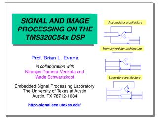
IMAGE PROCESSING ON THE TMS320C8X MULTIPROCESSOR DSP
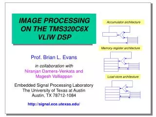
IMAGE PROCESSING ON THE TMS320C8X MULTIPROCESSOR DSP. Accumulator architecture. Memory-register architecture. Niranjan Damera-Venkata in collaboration with Prof. Brian L. Evans Embedded Signal Processing Laboratory The University of Texas at Austin Austin, TX 78712-1084
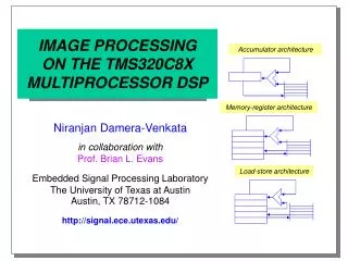

IMAGE PROCESSING ON THE TMS320C8X MULTIPROCESSOR DSP
E N D
Presentation Transcript
IMAGE PROCESSINGON THE TMS320C8XMULTIPROCESSOR DSP Accumulator architecture Memory-register architecture Niranjan Damera-Venkata in collaboration withProf. Brian L. Evans Embedded Signal Processing LaboratoryThe University of Texas at AustinAustin, TX 78712-1084 http://signal.ece.utexas.edu/ Load-store architecture
Outline • C80 Multimedia Video Processor • Master processor • Parallel fixed-point digital signal processors (DSPs) • Multitasking executive • Matrox C80 Genesis Development Board • Programming the C80 • Genesis Native Language • Genesis Native Library • Matrox Imaging Library • Parallel processor programming
PP3 PP2 PP1 PP0 MP TC 64 Crossbar network 10 kBRAM 10 kBRAM 10 kBRAM 10 kBRAM C80 Architecture MP: Master ProcessorPP: Parallel ProcessorTC: Transfer Controller Clock rate = 50 MHz
C80 Architecture • Four parallel processors • 32-bit DSP (32-bit integer arithmetic units) • Optimized for imaging applications • Master processor • 32-bit RISC processor • IEEE-754 floating point unit • Input/output units • Crossbar network: on-chip data transfer of 2.4 GB/s • Transfer controller: external data rate of 400 MB/s
Master Processor • Functions • Co-ordinate on-chip processing resources • Communicate with external devices • Perform floating-point calculations • Architecture • Load/store architecture • Pipelined floating-point unit • 4 KB instruction/data cache accessible by cross bar network • Designed for efficient execution of C code
Master Processor • 3-operand ALU • 31 32-bit registers • Register scoreboarding • 32-bit addresses • 4 double-precision floating-point accumulators • 10 KB RAM • 50 MIPS • Separate floating point multiply and add pipelines • Control registers
Register Scoreboarding • Synchronizes instruction and floating-point pipelines • Indicates when a pipeline stall is required • Registers waiting on a memory load completion • Registers waiting for results of previous floating-point instruction to be written • Scoreboard register • Scoreboard value for each register • Memory-load flag and floating-point-write flags are used to synchronize the pipeline
Master Processor Floating-Point Pipelines • Floating-point multiply pipeline • Integer multiplication • Single/double precision multiplication • Single/double precision division • Single/double precision square root • Multiply portion of multiply/accumulate operations • Pipeline stages • Unpack • Multiply (product of mantissas) • Normalize (pack sign, exponent, mantissa)
Master Processor Floating-Point Pipelines • Floating-point add pipeline • Floating point add • Single/double precision subtract and compare • Integer type conversions • Add/subtract portion of multiply accumulates • Pipeline stages • Unpack • Align (align binary point of the two mantissas) • Add (adds/subtracts mantissas) • Normalize (pack sign, exponent, mantissa)
Parallel Processors • Multiple pixel operations • Can execute a multiply, accumulate, an ALU operation, and two memory accesses in one cycle • Three-input ALU with 256 Boolean operations • Up to 10 operations per instruction per processor(500 million operations/s at 50 MHz per processor) • Bit field manipulation • Data merging • Bit to byte/half-word/word conversion • Accelerates variable length coding and decoding
Parallel Processors • 64-bit instruction word supports several parallel operations • Registers • 8 data • 10 address • 6 index • 20 other • Data Unit • 16x16 int. multiplier • Splittable 3-input ALU • 32-bit barrel rotator • Mask generator • Expander
Parallel Processors • Conditional operations • Conditional assignment of data unit results • Conditional source selection • Two address units • 3 hardware loop counters (zero-overhead looping) • Instruction cache • Algebraic assembly language
Parallel Processor Instruction Set • Data unit operators • Assignment operator(=) • Arithmetic operators(+, -, * , | |) • Bitwise Boolean operators( |, &, ^, ~) • Expand operator( @mf ) • Mask generator operator( % ) • Rotate operator( \\ ) • Shift operators(<<, >>)
Parallel Processor Instruction Set Data Unit Instruction Examples ; conditional assignment a15 = d6 - 31 ; a15 is read-as-zero register d6 = [lt] d6 + 1 ;increment d6 if it is less than 31 ; conditional source selection ; sr = 0x80000000 (n=1) d5 = d5 + d7[n]d6 ; Add d7 (if n=1) or d6 (if n=0) ; subtract and shift in parallel with unsigned multiply d7 = u d6*d5 ||d5 = d4 - d1 >> -d0 ; expand operation (uses mf and sr registers) ; mf=0x3, sr=0x20 (msize = byte, expand LSB) d1 = (d6 & @mf) | (d5 & ~@mf) ; mask generator operator (d6 & %7) ; d6 & 0x0000007F
Parallel Processor Instruction Set ; Multiple arithmetic example; sr is set to Asize field set to byte; 2 unsigned byte multiplications, subtractions and; shifts preformed using a ‘split’ multiplier d7 = um d6*d5 || d5 = d4 - d1 >> -d0 • Byte arithmetic speeds up operations by up to 4 times: speedup is not due to fewer memory accesses but rather due to hardware support for this feature
Parallel Processor Parallel Data Transfers • Two of the following operations can be specified in parallel with a data operation in a single cycle • Load/store • Address unit arithmetic • Move • Global data transfer am(address register) a8-a12, a14 • Local data transfer am can be a0-a4, a6 or a7
Parallel Processor Addressing Modes • Scaled indexing • Allows for data-independent indices • Useful for lookup table implementation ; a2-pointer to first element of a lookup table ; Data may be of any type (here it is word) d6 = w *(a2+[1]) ; Second element is loaded into d6 • Relative addressing • Allows for code independent of parallel processor ; dba automatically contains address of local PP RAM d6 = w *(dba +[1]) ; Second element in PP RAM -> d6
Parallel Processor Transfer Examples ; 2 loads in parallel x9 = w *(a8 + [5]) ; access to global memory ||d7 = w *(a1 + [x1]) ; access to local memory ; store to memory location *(a0 == 12) = x1 • External memory locations accessible by transfer controller
Multitasking Executive • Master processor software control of on-chip parallel tasks • Kernel • Software library of user-callable functions • Provides inter-task communication and synchronization • Presents uniprocessor-like interface to host • Software interface • Tasks on master processor issue commands to parallel processor command interpreter
Flow of Data and Control (C80) MasterProcessor Parallel Processors
Host Communications C80: Multimedia Video Processor (MVP)
Parallel Processor Processing Flow • Parallel processors may be configured in • parallel flow • pipelined flow • hybrid flow Parallelflow Pipelinedflow
Intertask Communication in Kernel • Messages • Message header specifies destination • Message body contains parameters and resource ids • Messages written to and read from ports • Counting semaphores • Bi-level signaling locations • Used to synchronize inter-task resource sharing • Example: ensure mutually exclusive memory access • 32-bit event flag register may be bound to ports/semaphores
The Kernel (cont.) • Kernel manages resources • Each port has pointers to the head and tail of • Message queue • Task descriptor queue • Messages are assigned to tasks on a first come first served basis (in order of message arrival) • Communication protocol implemented as a C function library
Task Scheduling • Task may be assigned a priority (0-31) when created • Lower priority tasks are preempted by higher priority tasks that are ready to execute • Multiple tasks may have the same priority • either wait in line • share processor in round robin fashion • voluntary task yield command • periodic interrupts for time-slice operation
Parallel Processor Command Interface • Parallel processors used as co-processors by master processor tasks • Parallel processor software is single threaded • Interprets a serial command stream • MP sends commands to parallel processor to fixed-size command buffers in local RAM Com. buf. 0 Com. buf. 1 Com. buf. 2 read write PP Mbox MP
Programming the C80 • Matrox Imaging Library • Portable across all Matrox boards • Does not require knowledge of C80 • Genesis native language and developers kit • Provides C function support for kernel and inter-task communication • Allows programming of parallel processors in assembly • Genesis Native Library • Pseudo C functions that may be called from host • Can specify opcodes for parallel processor functions
Steps in Using the Genesis Native Library • Initialize processor and allocate buffers using Matrox Imaging Library • Allocate processing threads • Set control registers/buffers for tasks • Send task to thread for execution • Synchronize tasks with host thread • Notify Matrox Imaging Library of buffer changes • Free resources
Programming on the Host • Create a C callable function (C-binding) Func /* Allocate thread, operation status buffer, buffers */ ... /* Start custom function (set OSB to 0 if not used) */ Func(Thread, SrcBuf, DstBuf, OSB); /* Host can now do other work while MVP is processing */ ... /* Wait for all threads to finish */ imSyncHost(Thread, OSB, IM_COMPLETED); • Operation status buffer (OSB) • Status codes for error checking • Synchronization
Programming on the Host /* Host C-binding for custom function*/ void Func(long Thread, long Src, long Dst, long OSB) { _IM_MSG_ST msg; /* Initialize message contents */ im_msg_start(&msg,OPCODE_Func, 2, “Func”); /* Pack function parameters in message */ im_msg_put_long(&msg,0,Src); im_msg_put_long(&msg,1,Dst); /* Send message to target thread and don’t wait */ im_msg_send(&msg,0,Thread,OSB,_IM_NO_WAIT); /*Report errors and clean up */ im_msg_end(&msg); }
Initializing the Task Table • To call a function from the host, its task descriptor (opcode) must be known to the command decoder on the Master Processor /* Add an external declaration for each new function */ extern void PrevFunc(); extern void Func(); /* Add a task table entry for each new function */ void(* mp_opcode_user[])() = { PrevFunc, /* _IM_START_USER_OPCODE + 0 */ Func, /* _IM_START_USER_OPCODE + 1 */ };
Programming the Master Processor /* include standard header file for MP code*/ #include “xyz.h” /* MVP code for custom function */ void Func(_IM_MSG_BODY_ST *msg) { MP_RESOURCE_ST *resource; .../*Allocate resource structure */ resource = mp_res_alloc(msg, MP_SYNCHRONOUS,”Func”); /*Unpack the parameters */ SrcBuf= mp_msg_get_long(msg, 0); DstBuf = mp_msg_get_long(msg,1); /*Allocate a device and a thread */ imDevAlloc(0,0,NULL,IM_DEFAULT,&Device); imThrAlloc(Device, 0, &Thread);
Programming the Master Processor /* Initialize parallel processors (next 2 slides) */ ...... /* Wait until processing has finished */ imSyncHost(Thread, 0, IM_COMPLETED); /* Free allocated resources */ mp_res_free(resource); }
Initializing Parallel Processors /* Allocate Parallel Processors in Master Processor code*/ mp_res_alloc_pps(resource, 1, 4) /* Alloc 4 PPs */ ... /* Determine how the job is to be divided */.../* Set up each Parallel Processor */ for(PP = 0; PP < NumPPS; PP++) { /* Get Parallel Processor number */ PPNum = mp_res_ppnum(resource, PP); /* Pass parameters to this Parallel Processor through its internal RAM */ mp_res_arg_pp(resource, PP, (void*) Param[PP]); /* Tell Parallel Processor which function to execute */ mp_res_set_entry_point(resource, PP, PP_func); }
Programming the Parallel Processors /* Start the parallel processors */ mp_res_start_pps(resource,pp_bit_mask); /* Wait until they finish */ mp_res_wait_pps(resource, pp_bit_mask); ; Parallel processor assembly code .include “ppdef.inc” .global _PP_func _PP_func pp_enter ;save return address(Macro) … pp_exit 0 ; return with value(Macro)
Optimizations using the Native Library • Use MIL only for setup/initialization • Minimize options • Use byte arithmetic as often as possible • Take advantage of 3-input ALU for multiple operations • Consider multithreading for multi-node systems • Pre-allocate all buffers • Avoid synchronous functions
Genesis Native Library Benchmarks Operation Time(ms) 3 x 3 convolution 5 x 5 convolution 3 x 3 erosion Bilinear interpolation FFT 7.6 23.9 19.2 6.5 240.0 Benchmarks are for a 512 x 512 image, using 8-bit signed kernels for convolution
Conclusion • Web resources • TI C8x literature and documentation http://www.ti.com/docs/psheets/man_dsp.htm • Matrox C80 based image processing products http://www.matrox.com/imaging • References • B. L. Evans, “EE379K-17 Real-Time DSP Laboratory,” UT Austin. http://www.ece.utexas.edu/~bevans/courses/realtime/ • B. L. Evans, “EE382C Embedded Software Systems,” UT Austin.http://www.ece.utexas.edu/~bevans/courses/ee382c/ • W. Lin, et. al. , “Real time H.263 video codec using parallel DSP”, IEEE Proc. Int. Conf. Image Processing, vol. 2, pp. 586-9, Oct. 1997.