STAR PXL Detector Sensor Cable Development
STAR PXL Detector Sensor Cable Development. LBNL Michal Szelezniak, Eric Anderssen, Leo Greiner, Thorsten Stezelberger, Joe Silber, Xiangming Sun, Chinh Vu, Howard Wieman UTA Jerry Hoffman, Jo Schambach IPHC Marc Winter CMOS group.


STAR PXL Detector Sensor Cable Development
E N D
Presentation Transcript
STAR PXL DetectorSensor Cable Development LBNL Michal Szelezniak, Eric Anderssen, Leo Greiner, Thorsten Stezelberger, Joe Silber, Xiangming Sun, Chinh Vu, Howard Wieman UTA Jerry Hoffman, Jo Schambach IPHC Marc Winter CMOS group Workshop on system integration of highly granular and thin vertex detectors September 6-9, 2011, Mont Sainte Odile, France
Outline • Introduction • PXL ladder characteristics • Cable development plan • Infrastructure testing board • Testing parameters • Testing results • Summary
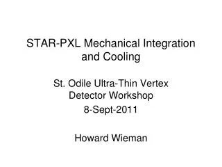
PXL detector mechanical design Aluminum conductor Ladder Flex Cable Mechanical support with kinematic mounts (insertion side) carbon fiber sector tubes (~ 200µm thick) Insertion from one side 2 layers 5 sectors / half (10 sectors total) 4 ladders/sector Ladder with 10 MAPS sensors (~ 2×2 cm each) 20 cm
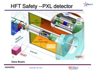
PXL electrical connection diagram • 10 parallel systems, each composed of: • 4 ladders (1 sector) • Mass Termination Board • Readout board
PXL ladder and cable cable bundle drivers kapton flex cable pixel chips adhesive composite backer adhesive wire bonds capacitors Ladder composition: Signal count on the cable for 2 generations of PXL sensors: *- signals required for prototyping and testing but not on final production boards. Phase-1 – challenging Ultimate – a bit easier
Current goal of cable development Preliminary Design: Hybrid Copper / Aluminum conductor flex cable • 2 layer Al conductor cable with vias in low mass region • 0.004” (100 µm) traces and 0.004” (100 µm) spaces • 70% fill factor • Conductor thickness in low mass region is 21 µm (Cu) or 32 µm (Al) • Kapton thickness is 25 µm. • Bond wire connection between Al and Cu cable sections. • Cable size is approximately 2.3 cm x 28 cm. Low mass region calculated X0 for Al conductor = 0.073 % Low mass region calculated X0 for Cu conductor = 0.232 %
PXL cable development plan • Infrastructure testing board (ITB) • Evaluate general design of running 10 sensors on a ladder • Find and test the working envelope of bypass capacitance and power supply and ground connections • Prototype detector cable– FR-4 with Cu traces • Correct size and the same layout geometry as the final cable • attempt to have the thickness of the Cu layer mimic the final cable to give the correct power and ground impedances • testing of this cable via digital output only • Prototype detector cable – Kapton with Cu traces • direct translation of the previous stage cable into a Kapton flex cable • Prototype detector cable– Kapton with Al traces
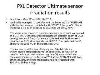
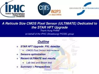
Infrastructure Testing Board (ITB) • Phase-1 prototype • Reticle size (~ 4 cm²) • Pixel pitch 30 μm • ~ 410 k pixels • Column parallel readout • Column discriminators • Binary readout of all pixels • Data multiplexed onto 4 LVDS outputs @ 160 MHz • Integration time 640 μs • Phase-2 prototype • Small mask adjustments to improve discriminator threshold dispersion • Phase-1 (Phase-2) sensor ITB with 10 sensors (Phase-1, 2) Analog readout - one sensor at a time Jumper selectable power source to each individual sensor In series replaceable resistor for each sensor power supply (analog and digital) Removable board level capacitor bypassing Removable individual sensor capacitor bypassing Readout over 2 m fine wire as per final ladders Readout through the full HFT data path including MTB, 160 MHz LVDS CLK All buffering and drivers use the same chips as the final ladder First prototype with full-thickness Phase-1, the second prototype with 50 µm Phase-2
ITB layout Analog readout buffers Ladder-like layout except for Power and GND Configuration Jumpers (9× Phase-1, 1× Phase-2)
Test parameters Sensor characterization – fit threshold scan data to the error function Faulty column Faulty column Noise FPN σ distribution µ distribution
Testing conditions NOTE: progressive capacitor removal (top-to-bottom) * A Phase-1-based PXL prototype would operate at <300 hits per sensor (inner layer)
Testing results – temperature Sensor performance is independent of temperature in this range average ITB temperature profile observed consistently throughout the test (results from the characteristics of the cooling system)
Testing results – noise in the digital readout Average noise and FPN extracted from threshold scan measurements FPN data marked with * excludes the first two sensors in the chain Error bars - standard deviation (σ) of the noise distribution.
Noise performance Low switching activity
Fixed pattern noise Low switching activity
Summary Phase-1 sensor performance appears independent of the number of high-frequency decoupling capacitors on the board (confirmed by analog and digital readout) Unaffected performance after removing all small capacitors associated with VDD, VDA and VCLP voltages. Test results obtained from threshold scans suggest that the bus-type power distribution provides, on average, a slightly better noise performance but with an increased FPN. Both effects are within 10-20 % and with the damaged sensor readout and limited testing capabilities can not be considered accurate. ITB equipped with 50 µm Phase-2 sensors is under test Stage 2 – FR4 prototype cable is in the design phase for the PXL production sensor (Ultimate)