Download
1 / 19
190 likes | 328 Vues
Girder Kinematics Modeling By Arsalan Jamialahmadi. Aim of the Study. To provide a model to study: Static deformation of the Micro-Control girder for the Main Beam of the CLIC two-beam prototype module. Maximum possible displacement of the beam axis on the maximum master movement(s).

E N D
Girder Kinematics Modeling By ArsalanJamialahmadi
Aim of the Study To provide a model to study: • Static deformation of the Micro-Control girder for the Main Beam of the CLIC two-beam prototype module. • Maximum possible displacement of the beam axis on the maximum master movement(s). • The parametric actuation of the conceptual design.
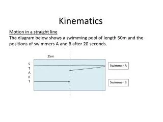
Modelling Micro-Control Technical Requirements: • Maximum vertical and lateral static deformation of 10 μm • Maximum girder weight of 240 kg • Maximum girder length is almost 2 m • Maximum sustainable dead weight of 400 kg/m • Maximum cross section of 320 mm × 150 mm • Maximum master actuation of ±0.3 mm • Maximum slave travel of ±3 mm Figure 1 – Master-Slave movement
Modelling • Girders and V-supports are integrated parts which are glued to each other and to the cradles. Cradles and actuators have multiple parts glued to each other. • Actuators, flexural joints and supports • Dummy load as accelerating structure • Z-direction movement at the end cradles suppressed • Roller compensated by frictionless contact Figure 2 – Two-Girder system
Modelling Table 1 – Material Properties
Modelling • Cylindrical joint for actuator • Supporting the structure • Flexural joints bear stress • Frictionless contact simulates rotation Figure 4 – Compensation of rotation by frictionless contact Figure 3 – Actuator modelling
Modelling Table 2 – Performed studies Table 3 – Number of Elements for different configurations Note: Girder with spring points out the girder system in which spring serves as the master-slave movement provider for actuators.
Results Static deflection – no actuation Table 4 – Static deflection results Note: The load/actuator and the Z-direction movement suppression are the contributors to the increase of deflection and stress. The values of deflection are lower compared to the values given by Micro-Control without pre-stress. Figure 5 – Static deflection with no actuation
Results Static deflection – maximum actuation Applied abbreviations: a,b,c Actuator position on cradle 1,2,3 Cradle number p,n Positive or negative F,R Front and rear Figure 6 – Displacement b1p-c1n
Results Static deflection – maximum actuation Table 5 – Deflection values for One-Girder system with spring Note: Displacements are in micrometer
Results Static deflection – maximum actuation Table 5 gives the following information: Slave movement of actuators with respect to maximum actuation of the master movement(s). Beam axis movement with respect to maximum actuation of the master movement(s). Angle of rotation of beam axis with respect to its initial position. Figure 7 – Two-Girder system maximum actuation a2p-b2p-c2p
Results Modal Analysis Table 6 – Resonance frequencies for Two-Girder system Note: The resonance values of the system with spring might be used for comparison only For this system, the first resonance frequency estimate from Micro-Control analysis is 49.8 Hz.
Results Modal Analysis Figure 8 – First 4 resonance frequencies and mode shapes of the Two-Girder system with fixed actuators
Results Parametric Study • Overview: • Number of input variables: 3 • Number of output variables: 9 (1-Girder) or 18 (2-Girder) • The range for input variables are ±0.3 mm. • The 3 input variables are the two vertical and one horizontal actuator movements of one cradle. • Output variables give the changes in x, y and z coordinates of the beam axis ends for each girder. • Results (outputs) are shown as variation diagrams of two input variables while the third input variable remains constant.
Results Parametric Study Two vertical actuators of the first cradle are moving while the horizontal actuator is set to be fixed at zero. By having the same amount of actuation for the vertical actuators, front point of the beam axis will not have any displacement component in x-direction. Figure 9 – Parametric study of One-Girder system. F1x is a function of three variables a1,b1 and c1. Here c1=0
Results Parametric Study The second vertical (b1) and the horizontal actuator (c1) from the first cradle are moving while the first vertical actuator (a1) is set to be fixed at 0.156 mm displacement. By having the b1 constant, rear point of the beam axis will not have any displacement component in y-direction. Figure 10 – Parametric study of One-Girder system. Ry1 is a function of three variables a1, b1 and c1. Here a1=0.156
Conclusions • Static deformation values are relative values as the pre-stress option was not possible with ANSYS. If pre-stress is considered, then only static deflection values are to be changed. • Worst case deflection is not passing the ±3 mm limits. • Lowest resonance frequency is 45.5 Hz. • Parametric study is a suitable tool to locate the beam axis
Further Work • The mechanism of master-slave movement needs to be studied more thoroughly. The snake system kinematics is governing. • Modal analysis can be done again with accelerating structure for comparison purpose. • The more the number of girders, the more precise results but heavier model at the same time! • Number of input variables of the parametric study can be increased to consider 6 actuator movements for alignment study. • A thorough report of this work will be written for through description of the results.