Download
1 / 32
340 likes | 436 Vues
Understand current, resistance, and DC circuits, covering Kirchhoff’s Laws, Ohm's Law, power, elements in circuits, and practical examples. Learn about current density, drift speed, resistivity, conductivity, and how circuit elements interact. Includes calculations and explanations.

E N D
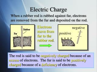
Electricity and MagnetismLecture 07 - Physics 121Current, Resistance, DC Circuits: Y&F Chapter 25 Sect. 1-5Kirchhoff’s Laws: Y&F Chapter 26 Sect. 1 • Currents and Charge • Electric Current i • Current Density J • Drift Speed, Charge Carrier Collisions • Resistance, Resistivity, Conductivity • Ohm’s Law • Power in Electric Circuits • Examples • Circuit Element Definitions • Kirchhoff’s Rules • EMF’s - “Pumping” Charges, Ideal and real EMFs • Work, Energy, and EMF • Simple Single Loop and Multi-Loop Circuits using Kirchhoff Rules • Equivalent Series and Parallel Resistance formulas using Kirchhoff Rules.
Units: 1 Ampere = 1 Coulomb per second Convention: flow is from + to – as if free charges are + + - Current flowing through each cross-section of a wire is the same i Current density J may vary [J] = current/area At any Node (Junction) i1+i2=i3 Kirchhoff’s Rules: (preview) • Current (Node) Rule: Scurrents in = Scurrents out at any node • Voltage (Loop) Rule: SDV’s = 0 for any closed path • Voltage sources (EMFs, electro-motive forces) or current sources can supply energy to a circuit (or absorb it). • Resistances dissipate energy as heat. • Capacitances and Inductances store energy in E or B fields. Roles of circuit elements i1 i3 i2 Definition of Current : Net rate of charge flow through some area Charge / current is conserved - charge does not pile up or vanish
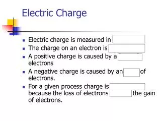
1 A 5 A 2 A 3 A 2 A 3 A 1 A i = 7 A 8 A 6 A Junction Rule Example – Current Conservation 7-1: What is the value of the current marked i ? • 1 A. • 2 A. • 5 A. • 7 A. • Cannot determine from information given.
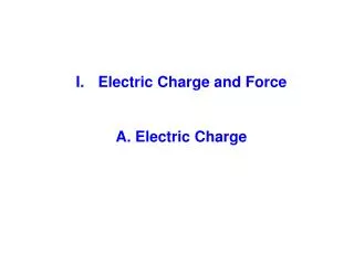
Small current density A’ A i + - J’ = i / A’ (small) J = i / A (large) High current density i If density is uniform: units: Amperes/m2 If density is non-uniform: resistivity conductivity • What makes current flow • in a conductor? • Not in equilibrium if DV not zero • E not required to be zero Do electrons in a current keep accelerating? • Yes, for isolated charges in vacuum. • No, in a conducting solid, liquid, gas • Recall: terminal velocity for falling object (collisions => drift speed) Current density J: Current / Unit Area (Vector) Conductor width varies …… but …. same current crosses larger or smaller surfaces. What varies is current density J.
E field in solid wire drives current. APPLIED FIELD NOT ZERO Accelerating charges collide frequently with fixed ions and flow with drift velocity vd • Thermal motions (random motions) have speed • Drift speed is tiny compared with thermal motions. • Copper drift speed is 10-8 – 10-4 m/s. Drift Speed Formulas: APPLIED FIELD = ZERO Charges in random motion left flow = right flow q = charge on each carrier + + - - s = v E D qn Note: Electrons flow leftward in sketch but vd and J are still to the right. Collisions with ions & impurities, etc. cause resistance Charges move at constant drift speed vD:
ions/cm3 m/s cm3/m3 coul/ion A./m2 EXAMPLE: Calculate the current density Jions for ions in a gas • Assume: • Doubly charged positive ions • Density n = 2 x 10⁸ ions/cm3 • Ion drift speed vd = 105 m/s Find Jions – the current density for the ions only (forget Jelectrons)
Increasing the Current 7-2: When you increase the current in a wire, what changes and what is constant? • The density of charge carriers stays the same, and the drift speed increases. • The drift speed stays the same, and the number of charge carriers increases. • The charge carried by each charge carrier increases. • The current density decreases. • None of the above
A E i i DV R L V Circuit Diagram Resistivity “r” : Property of a material itself Does not depend on size/geometry of a sample • The resistance of a device depends on resistivity r and also depends on shape • For a given shape, different materials produce different currents for same DV • Assume cylindrical resistors For insulators: r infinity Definition of Resistance : Ratio of current flowing through a specific conductor to applied potential difference. R depends on the material & geometry Note: C= Q/DV – inverse to R Apply voltage to a wire made of a good conductor. - very large current flows so R is small. Apply voltage to a poor conductor like carbon - tiny current flows so R is very large. Ohm’s Law means: R is independent of applied voltage
resistivity proportional to length resistance inversely proportional to cross section area EXAMPLE: Find R for a 10 m long iron wire, 1 mm in diameter Find the potential difference across R if i = 10 A. (Amperes) EXAMPLE: Find resistivity of a wire with R = 50 mW, diameter d = 1 mm, length L = 2 m Use a table to identify material. Not Cu or Al, possibly an alloy Example: calculating resistance or resistivity
A E i i Simple linear model of resistivity: a = temperature coefficient DV L Change the temperature from reference T0 to T Coefficient a depends on the material Conductivity is the reciprocal of resistivity Definition: Resistivity depends on temperature: • Resistivity depends on temperature: Higher temperature greater thermal motion more collisions higher resistance. r in W.m @ 20o C. 1.72 x 10⁻⁸ copper 9.7 x 10⁻⁸ iron 2.30 x 10+3 pure silicon Reference Temperature SOME SAMPLE RESISTIVITY VALUES
R V Circuit Diagram Current Through a Resistor 7-3: What is the current through the resistor in the following circuit, if DV = 20 V and R = 100 W? • 20 mA. • 5 mA. • 0.2 A. • 200 A. • 5 A.
R V Circuit Diagram Current Through a Resistor 7-4: The current in the preceding circuit is doubled. Which of the following changes might have happened? • The voltage across the resistor might have doubled. • The resistance of the resistor might have doubled. • The resistance and voltage might have both doubled. • The voltage across the resistor may have dropped by a factor of 2. • The resistance of the resistor may have dropped by a factor of 2. Note: there might be more than 1 right answer
(R could depend on applied V) Definitions of resistance: (rcould depend on E) • Definition of OHMIC conductors and devices: • Ratio of voltage drop to current is constant – NO dependance on applied voltage. • Voltage drop across a circuit element equals CONSTANT resistance times current. • Resistivity does not depend on magnitude or direction of applied voltage Ohmic Materials e.g., metals, carbon,… Non-Ohmic Materials e.g., semiconductor diodes band gap varying slope = 1/R constant slope = 1/R OHMIC CONDITION is CONSTANT Ohm’s Law and Ohmic materials
i • Apply voltage drop V across load resistor • Current flows through load which dissipates energy - irreversible • The EMF (battery) does work by expending potential energy, • It holds potential V and current i constant, 1 + LOAD V As charge dq flows from 1 to 2 it loses P.E. = dU - Potential V is PE / unit charge - Charge = current x time 2 - i Resistors Dissipate Power - Irreversible
EXAMPLE: EXAMPLE: EXAMPLE:
Demonstration Source: Pearson Study Area - VTD https://mediaplayer.pearsoncmg.com/assets/secs-vtd36_irlosses Chapter 25 Resistance in Copper and Nichrome Power dissipated = current2 x resistance Discussion: • What made one paper sample ignite but not the other? • What was different for the copper and Nichrome wire?
2 1 Ideal basic circuit elements: Passive: resistance, capacitance, inductance or C Active: voltage sources (EMF’s), current sources • Ideal independent voltage source: • zero internal resistance • constant vs for any load + DC battery + AC - - vs is E DC • Ideal independent current source: • constant is regardless of load vs Dependent voltage or current sources: depend on a control voltage or current generated elsewhere within a circuit C L R Basic Circuit Elements and Symbols Basic circuit elements have two terminals Generic symbol:
Circuits consist of: ESSENTIAL NODES (junctions)...and … ESSENTIAL BRANCHES (elements connected in series, one current/branch) i1 i i i2 ANALYSIS METHOD: Kirchhoff’S LAWS or RULES Current (Junction) Rule: Charge conservation Energy conservation Loop (Voltage) Rule: RESISTANCE: POWER: slope = 1/R i R is independent of DV or i OHM’s LAW: DV Circuit Analysis / Circuit Model
What EMFs do: + - i Power supplied by EMF: E R i CONVENTION: Positive charges flow - from + to – outside of EMF - from – to + inside EMF Power dissipated by resistor: • raise charges to higher potential energy, i.e. move + charges from low to high potential • maintain constant potential at terminals for any value of current • do work dW = Edq on charges (using chemical energy in batteries) • Unit: volts (V). Symbol: script E. • Types of EMFs: batteries, electric generators, solar cells, fuel cells, etc. • DC versus AC
Pabsorbed = dot product of Vrise with i (active sign convention) + + + 1 i - - - Circuit element absorbs power for V opposed to i Voltage rise: 2 P = - Vi V V Circuit element supplies power for V parallel to i 1 P = + Vi i V 2 Note: Some EE circuits texts use passive convention: treat Vdrop as positive. Is a Component Supplying or Dissipating Power?
Real EMF device • Open switch: EMF still =E • - r = internal EMF resistance in • series, usually small • Closed switch: • - V = E – ir across load, Pckt= iV • - Power dissipated in EMF • Pemf = i(E-V) = i2r Multiple EMFs • Assume EB > EA (ideal EMF’s) • Which way does current i flow? • Apply kirchhoff Laws to find current • Answer: From EB to EA (CCW) • EB does + work, loses energy • EA is charged up, does negative work • R converts PE to heat • Load (motor or other) produces • motion and/or heat R Ideal EMF device • Zero internal battery resistance • Open switch: EMF = E • - zero current, zero power • Closed switch: EMF Eis • applied across load circuit • - current & power not zero
Rules for generating circuit equations from the Kirchhoff Loop Rule: Multi-loop circuits. Assume unknown currents • The sum of voltage changes is zero around every closed loop in a multi-loop circuit. • Define: A branch (essential branch) is a series combination of circuit elements • between essential nodes. • Each branch has exactly one current flowing in it through all components in series. • Traversing one closed loop generates an equation. There may be several branches. • Assume either current direction in each branch. Minus signs may appear in the result. • While traversing a closed loop, a test charge might traverse many branches,\ • flowing with or against assumed current directions. • When crossing a resistance with the assumed current direction, add an equation • term for a voltage drop DV = - iR. Otherwise, write voltage gain of DV = +iR. • When crossing EMFs from – to +, write DV = +E, since the potential rises. • If traversing EMF from + to minus write DV= -E. • The ‘dot’ product i.E determines whether power is actually supplied or dissipated.
Kirchhoff Loop Rule example: Follow circuit from a to b to a, same direction as i D Potential around the circuit = 0 E E Power in external ckt P = iVba = i(E – ir) P = iE – i2r circuit dissipation battery drain battery dissipation Single loop circuit with battery & internal resistance r
CONCLUSION: The equivalent resistance for a series combination is the sum of the individual resistances and is always greater than any one of them. Example: Equivalent resistance for resistors in series Junction Rule: The current through all of the resistances in series (a single essential branch) is identical. No information from Junction/Current/Node Rule Loop Rule: The sum of the potential differences around a closed loop path equals zero. Only one loop path exists: The equivalent circuit replaces the series resistors with a single equivalent resistance Req:same E, same i as above. inverse of series capacitance rule
Example: Equivalent resistance for resistors in parallel Loop Rule: The potential differences across each of the 4 parallel branches are the same. There are four unknown currents. Apply loop rule to 3 paths. i not in these equations Junction Rule: The sum of the currents flowing in equals the sum of the currents flowing out. Combine equations for all the upper junctions at “a” (same at “b”). The equivalent circuit replaces the series resistors with a single equivalent resistance: same E, same i as above. CONCLUSION: The reciprocal of the equivalent resistance for a parallel combination is the sum of the individual reciprocal resistances and is always smaller than any one of them. inverse of parallel capacitance rule
Demonstration Source: Pearson Study Area - VTD Chapter 26 Bulbs Connected in Series and Parallel Circuits https://mediaplayer.pearsoncmg.com/assets/secs-vtd37_seriesparallel Discussion: • Why did some of the bulbs look dimmer and others looked brighter? • How do the equivalent resistances affect what you saw?
Resistors in series and parallel 7-7: Four identical resistors are connected as shown in the figure. Find the equivalent resistance between points a and c. • 4 R. • 3 R. • 2.5 R. • 0.4 R. • Cannot determine from information given. c R R R R a
Capacitors in series and parallel 7-8: Four identical capacitors are connected as shown in figure. Find the equivalent capacitance between points a and c. • 4 C. • 3 C. • 2.5 C. • 0.4 C. • Cannot determine from information given. c C C C C a
R1= 10 W i R2= 7 W E = 7 V R3= 8 W + + - - i i1 i2 R1 R2 E = 9 V i EXAMPLE: Find i, V1, V2, V3, P1, P2, P3 EXAMPLE: Find currents and voltage drops
i i R1= 10 W E2 = 3 V E1 = 8 V R2= 15 W + + - - A battery (EMF) absorbs power (charges up) when I is opposite to E EXAMPLE: MULTIPLE BATTERIES SINGLE LOOP
Suppose diameter is 2 mm instead. Find J’: Current i is unchanged Calculate the drift velocity for the 1 mm wire as above? About 3 m/year !! Calculating n for copper: One conduction electron per atom EXAMPLE: Find the average current density J in a copper wire whose diameter is 1 mm carrying current of i = 1 ma. So why do electrical signals on wires seem to travel at the speed of light (300,000 km/s)?