Download
1 / 35
350 likes | 626 Vues
Experience from CMS tracker cooling: Tracker Outer Barrel (TOB) Antti Onnela TOB Project Engineer, CERN-PH-DT2. A few words on CMS Tracker and its cooling Details of the TOB cooling. CMS. Tracker services routed around solenoid magnet and along the central Wheel 0. CMS Tracker.

E N D
Experience from CMS tracker cooling: Tracker Outer Barrel (TOB)Antti OnnelaTOB Project Engineer, CERN-PH-DT2 A few words on CMS Tracker and its cooling Details of the TOB cooling
CMS Tracker services routed around solenoid magnet and along the central Wheel 0
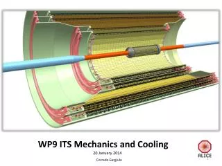
CMS Tracker Outer Barrel - TOB - End Caps – TEC (at the two ends, one shown only) Inner Barrel & Disks - TIB & TID - 2,4 m Pixel detector 5.4 m Beam pipe 210 m2 of silicon sensors 6,136 Thin detectors (1 sensor) 9,096 Thick detectors (2 sensors) 9,648,128 electronics channels Support Tube & Thermal Screen •24.4m3 closed volume •operating temperature –10C
CMS Tracker (Silicon strip) + control electr.+ optical links + cables TOB: 5’208 x Tracker all: 15’232 x • 15 kW • 50 kW
Tracker Cooling • Remove heat-load, maintain sensors at -10 ºC, but no heat/cold load to other CMS sub-systems (ECAL especially !) • Liquid-phase C6F14 • Fluid temperature: (+10 ºC) … -20 ºC … (-30 ºC) • Fluid pressure: < 2 bar (pixels), < 6 bar (strip) • Cooling units in UXC balconies • Cooled by salt-water (brine) at -45 ºC from USC
Tracker Cooling • Active thermal screen, thickness 13 mm, next to Support Tube • Cold panels in aluminium (2 sheets of 0.7 mm each, hot-roll bonded) • 10 mm of Rohacell foam insulation • Heating foils in Kapton/Inconel • At Tube ends only “passive” elements (honey-comb end-plates, cable/connector volumes) • Dry N2 flushing in every TK sub-detector, TK end-region and in patch-panels (?) inside CMS • N2 fed to the TK volume along thermal screen cooling pipes, which are always at “Tracker temperature”
Tracker Cooling • Materials used in the cooling pipework (a lot of history…): • Feed-pipes: soft copper • Brazed and solderered connections, double O-ring fittings at Tracker ends • Pixel: Aluminium, rubber hoses (replacing possible) • TIB/TID: Aluminium, • welded joints, compression fittings • TEC: Titanium in petals, manifolds in stainless steel, • welded joints, compression fittings • TOB: Copper-nickel • Brazed and soft soldered joints with brass connections
TOB • Support Wheel • 4 Disks with 344 openings • 6 joining Cylinders • “Rods” • With 6 or 12 modules • 688 x
TOB Rod Frame 113 pieces / rod frame 760 rod frames in total (688 needed + 72 spares) = 85880 pieces in total ! Capillary glued in jigs at RT
Modules on the Rod Carbon-fibre (Mitsubishi K13D2U) / Cyanate-ester (YLA CE3) support frame with aluminium contact plates attached against 4 module supports Module supports in contact with cooling pipe
Module supports and pipe A groove in the module support insert and a cap enclose the pipe. Capillar glue (Araldite 2020) injected, but pipe treated with mold-release to allow pipe to slide inside this “tube”. Copper-nickel 70/30 pipe (Ø2.2 mm or Ø2.2 mm, 0.1 mm wall)
Testing modules and rods From testing of single and double modules to testing of complete rods • Tests performed in –20 °C. • Tmax = 10 °C between silicon and coolant – OK ! • Equal cooling in all module positions along the rod. • Reliable testing is not simple ! Modules have excellent heat exchange with sourrounding volume.
Soldered connections A test-set of soldered connections.Leak-tightness tested to 15 bar pressure, and thermal cycling down to -196C. Copper-nickel 70/30 pipes and brass connection pieces Soldered with eutectic Sn62% - Pb36% -Ag2% with rosin flux (ERSIN 362)
Test connections WITHOUT soldering Custom-made quick-connects
Production: Leak testing of rod pipes “Bubble test” of bent and soldered rod pipes with water and 20 bar air 10 % of the 850 pipes produced leaked ! All leaks in the pipe wall (well known problem in Atlas…)
Production: Leak testing of complete rods Helium leak-detector, test in vacuum mode. Alarm limit 10^-8 mbarl/s (bubble-test at best ~10^-5 mbarl/s). Only ~ 1% of pipes found now leaking, even if tighter test and rods gone through all production chain, thermal cycling, transports, etc. Leak repair by soldering.
Relevance of the Leaks ? • Correspondence between Helium leak and C6F14 leak studied using final type rod pipes with leaks spotted with He-test [Erkki Anttila, Helsinki Institute of Physics ]
Relevance of the Leaks ? Bubble-test can spot leaks down to ~10 g/a scale. With He testing (1000-100’000x more sensitive) drop to insignificant leak levels for fluid loss. However tiny leaks can be signs of weak-spots, e.g. in solder joints, and need to take serious for long operation. Additional tests planned to verify results, and eliminate test system leaks.
Coolant distribution Distribution pipes of all 6 layers serving the 22 cooling segments
Soldering to the manifolds Humid foam (not visible here)to cool/protect earlier Rod pipe solder and glues Small amount of solderin the iron tip to improve thermal contact Fume extraction Lessons: Good local fume extraction is enough, no need for protection foil Requires stable hands, not for everybody! Brass connection pieces which were previously brazed were such oxidized than normal cleaning was not enough. Need to mechanically clean the surfaces for subsequent soft soldering.
Experiences • Liquid-phase fluorocarbon cooling: • Simple and easily manageable for design and production in multi-sites • Adequate cooling performance for the modest power densities in the CMS silicon strip detectors • Heavy, but with ~2 mm diameter pipes really significant only at the manifold areas • Main problem: Operation temp below dew point leads to difficulties in the thermal management and insulation of the feeding pipes outside the well-controlled (dry) tracking volume • Can be used for the cooling of the cables, but making this to really function correctly is not obvious due different running conditions of the detector
Experiences • Copper-nickel + brass + soldered joints: • One real problem: quality of the thin-wall CuNi pipes • Another worry: activation of silver (in solder) • Soldering, even in-situ, works ok (need tools and methods), surfaces must be correctly prepared ! • Easy soldering yields also possibility to repair, and simple electrical connections • Leak-testing • Absolutely necessary, and should be thought and tried in advance before production • Bubble-test ok for coarse QC, but rather slow and operator dependant • Happy with He –leak testing: simple to use, high-precision (very small leak-sizes, precise localization of leaks)
Experiences • Operational experience … very soon !
Soldering Unexpected difficulties with the soldering: Brass connection pieces more oxidized and dirty than what we were used to. These pieces have now a longer history. → Need to prepare the surfaces more carefully, before having the pieces in the Wheel. Taken now into account in the planning for final assembly.
Soldering Silicon module on one side 35 mm Clean Alu foil on other side
Unsoldering Pipe removal can also be done without cutting the connection pipe, but this way the unsoldering is simpler.
Leak testing Three weak solderings found with 10^-4 - 10^-6 mbarl/s leaks (all amongst first solder joints made).Connections disconnected, cleaned and resoldered:All connections then leak tight (alarm limit at 1x10^-7 mbarl/s)
Testing of a segment 12 m A complete TOB cooling segment with 19 “rods” installed and tested in the tracker cold-room • Tests in room temperature and –25 °C. • Successful and simple filling and draining. • Equal cooling performance in all parallel rods. • Δp in segment (2.4 bar) higher than calculated (1.7 bar) • Local pressure drops in manifolds
Coolant distribution measured with a final cooling segment in the TOB Uniform temperature profile → equal distribution of coolant to all rods.
ALL rods pass through thermal cycling Several cycles between RT and -20C Detectors biased Modified commercial chest freezer, max 8 rods at a time [by Paul Tipton, Univ. of Rochester] Thermal cycling