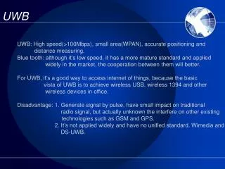
UWB
UWB. Ian O’Donnell, Bob Brodersen. Berkeley Wireless Research Center Univ. of California, Berkeley. The Known World. Traditional Radio Spectrum Allocation:. Narrowband (Bandwidth tightly constrained) Relatively small amount of unlicensed BW (Bandwidth scarcity)

UWB
E N D
Presentation Transcript
UWB Ian O’Donnell, Bob Brodersen Berkeley Wireless Research Center Univ. of California, Berkeley
The Known World Traditional Radio Spectrum Allocation: • Narrowband • (Bandwidth tightly constrained) • Relatively small amount of unlicensed BW • (Bandwidth scarcity) • Spectrum Auctions ($$$) • Current spectrum poorly utilized Radios Built/Researched To Those Specifications: • fcarrier, channel BW, adj. chan. interference, modulation, PTX, RX sensitivity (NF), transmit distance, etc.
Currently Available LAN/PAN Radios Naïve Plot: Transceiver Power vs. Throughput Sources: ISSCC 2001-2004; JSSC 1998; ISCAS 2000; RFM; AD; Honeywell; Maxstream; OKW; IA(Ezradio); Chipcon; Atmel; 802.15.3a 802.15.4a Bluetooth, 802.11b, PicoRadio, c/o M. J. Ammer UWB • 1Mbps/ • 1mW • (BIT) • 110Mbps/ • 100mW • (802.15.3a) Throughput (bps) TX+RX Power (mW)
ANALOG: I A/D DIGITAL: LNA MIXER Q A/D F SYNTH D/A PA MIXER D/A ANALOG: I LNA A/D DIGITAL: D/A PA The Lure of UWB Conventional Integrated Narrowband Transceiver: UWB Promises: • Simplicity • Low Cost • Integration • Low Power • Large BW • Ranging • Unlicensed Operation • Coexistence UWB “Mostly Digital” Radio:
FCC Regulations • Categorizes three types of UWB devices: • Imaging systems; including ground-penetrating RADAR (GPR), through wall and medical imaging, and surveillance devices • Vehicular RADAR systems • Communication and measurement systems • Specifies: • Minimum BW (-10dB) of 500MHz or 0.2*fcarrier • Peak to average ratio 20dB (max) • Roughly two bands: 0-960 MHz, 3.1-10.6 GHz • 3m EIRP power levels (generally part 15) • ~ -20dBm total power in 0-960 MHz • ~ -2dBm total power in 3.1-10.6 GHz But, Physical signaling not specified. Power levels are low. (Shorter range)
Bits/sec/Hz 4 3 2 1 Eb/N0 -5db 15 db 10 db 5 db 1/2 1/4 1/8 1/16 UWB – Terra Incognita Energy Limited Bandwidth Limited UWB Usual goal Low signal to noise ratio: Bandwidth inefficient. (Here Thar Be Monsters!)
Standards: 802.15.3a • Seems to be the main focus of the UWB in the media • (Hey, bandwidth is sexy, and who likes wires anyways?) • Purpose: • Small form-factor, short range (due to limited TX power) but very high rate communication. Ideally less power/expense than WLAN (802.11a) • Goal: • 110Mbps at 10m in 100mW • 200Mbps at 4m in 250mW • Optional 480Mbps at whatever distance can be achieved • Standard Stalemate: • Consumer Electronic Companies (BOK) vs. • PC Companies (OFDM) • Intel’s “Wireless USB” announcement may trump standard
Standards: 802.15.4a • Low Rate Alternative PHY for WPAN • Principal interest in ultra low power communication and precise ranging with scalable data rate/range. • PHY Technical Requirements • Data rate: 1kbps up to 1Mbps (aggregators) • Range 0-30m • Power consumption several months to years • Precision ranging (Location awareness 10’s cm to 1m) • Dynamic networking • Antenna non-directional • Form factor appropriate for sensor network/RF tags • Motion tracking (pedestrian/industrial vehicle, opt. automobile) • Robust operation • Call for Proposals Sept. ’04; Done by Q2 2006
802.15.4a Applications • Categories of Applications: • Safety/Health Monitoring • “Man down”, search and rescue, situation awareness, etc. • Personnel Security • Tracking child/prisoner/guard, surveillance, auto car/workstation locks, etc. • Logistics • Tracking wildlife/cattle/workforce/customers/packages, space utilization measurements, robotic mowing/farming, call fwd, etc. • Industrial Inventory Control • Autonomous manifesting/meter reading, asset tracking, etc. • Industrial Process Control and Maintenance • Wireless sensor networks, robotics, anti-collision, remote sense/service • Home Sensing, Control and Media Delivery • Gaming, streaming media, media redirection, smart tags, HVAC control, etc. • Communication • PAN, Cordless phones, routing (IEEE P802.15-03-04420-01-004a) Many disparate applications/markets.
Why Use 0-1GHz? Considered to be “crowded” or “dirty” spectrum (Due to the historical development of wireless, it is the heaviest used part of the spectrum.) • Why is it desirable? • Good material penetration • Longer transmit distances • Low frequency is easier for design • Lower power consumption (lower frequency operation) • What is wrong with it? • Lower frequencies mean larger passive values for filters, harder to integrate • Larger antennas (related to l) • That aforementioned interference problem from preexisting users… Fig. c/o Bob Scholtz
Spectrum Usage: 0-1GHz Some Interferers: FM: 88-108 MHz TV: 54-88 MHz (VHF 2-6) 174-216MHz (VHF 7-13) 470-806MHz (UHF 14-69) Taxi: 157, 452, 457MHz Police: 154-6, 158-9, 460, 465 MHz GMRS: 462, 467MHz ISM: 902-928MHz Cell phone:824-849MHz, 870-893MHz Pager: 929-930MHz Maybe not as bad as expected…
Pulse-Based Throughput of 0-1GHz • Using previous interference, capacity is 28.5Gb/s! (3m) • Even with noise equal to the mask, there is ~2Gb/s (3m) • If you use a pulse, an optimistic link budget (using prev. interference) yields: • ~100Mbit at 3m • 1Mbit at ~60m • FCC Mask: Part 15.209 • (Class C Emission) for low-frequency imaging systems
Why Ranging Is “For Free” • Radios need to be synchronized to communicate. • Synchronization requires fine timing resolution for UWB pulses. • That timing resolution (~500ps for 2GSa/s) may be easily used to measure time-of-flight. (~0.5 ft) Can improve time-of-flight measurement by examining correlation profile, allowing for sub-500ps resolution (on the order of inches) with 0-1GHz.
The UWB Opportunity • What is “hard” about UWB? • Antenna (omni, small form-factor, efficient coupling) • Interference (filtering, tolerating in-band interferers) • Spectral mask compliance (pulse/waveform generation) • Fast acquisition, Efficient synchronization • Efficient channel estimation • Low power consumption w/ 1GHz BW and 2GSa/s ADC’s • Exploiting range information (networking) • System exploration space is large But for researchers, this is exciting stuff !
Research Areas • UWB Channel/Interference Meas./Modeling • Antenna Research • Circuit Research: • Antenna Co-Design • Pulse generation • System Design: • Pulse-based • OFDM • Transmit-reference • 1-bit “mostly-digital” • Signal Processing/Algorithms: • Rapid Acquisition, Synch, Locationing, Imaging • CAD Tools (Simulation and Design) • Min. power consumption • Min. jitter • Frequency-based (bandpass) • Orthogonal projection • Subsampling • Oversampling
UWB Channel Research/Measurements • Spatial Capacity – • Recent Ph.D. Thesis • (Ada Poon) • Spatial Channel Measurements • (Jing Yang) • Sweep TX/RX antenna arrays over 360o azimuth, -40o to 90o elevation • TX from pulse generator • 20GSa/sec Scope as RX
Small Antenna Modeling • Desirable UWB antenna characteristics: • Small form-factor • Broadband • Omni-directional 6cm Dipole Antenna Input Impedance • For 0-1GHz, ‘small’ is electrically small: • E-fields nearly same in all dir • Simple circuit model • Can estimate radiated E-field in SPICE (Co-Design) • But, antenna is inherently narrowband: • Inefficient radiation • 50 W radiation resistance not possible over whole BW c/o Stanley Wang
Antenna/Circuit Interface STMicroelectronics 0.13um CMOS process • Transmitter: Pulse generation • Total area: 0.49mm2 • 1.2V Vdd • Differential drivers • 16 levels of drive • Receiver: LNA • Current-reuse allows for 50 W Zin with 1mW consumption • Layout area: 59mm x 45mm • Coupling capacitors off-chip c/o Stanley Wang
Berkeley Impulse Transceiver (BIT) Targeting Sensor Network Application • Specifications: • 100kbps over 10m with 10-3 BER • 1mW total (TX+RX) power consumption • 0-1GHz bandwidth ADC GAIN CLK DIGITAL TX • First all-CMOS integrated UWB transceiver • for comm. and ranging/locationing • Aggressive low-power design • “Mostly-digital” approach, simplify analog front-end • Provide flexible platform for further research
Pulse Reception Only process data from a window of time: Voltage time Sample Time Pulse Reception Window Pulse Transmission Rate Analog On Sampling On Digital Off Analog Off Sampling Off Digital On Analog Off Sampling Off Digital Off Analog On Sampling On Digital Off Receiver Operation time
Transceiver Power Estimate Always On ~8 mW (32 Mpulse/s) Duty-Cycling Starts GAIN DIGITAL BIAS A/D OSC TX DLL CONTROL Duty-Cycled To ~1mW (1 Mpulse/s)
G V[31:0] TX Transceiver Status O.K., this time for sure: Chip will tape-out this summer! Gain stages layout left, and TX block, then final assembly. Process: 0.13um ST Microelectronics Size: ~15mm2 Digital: 3.3mm x 3.3mm; 245,000 StdCells Analog: 3.3mm x 1.1mm
System Exploration/Prototyping Berkeley Impulse Transceiver (BIT) (0-1GHz) Also designed as flexible testbed: • Different antennas/LNA impedance • Variable transmit power • Variable pulse rate • Programmable pulse matched filter • Adjustable synch/data recovery • Independent synch/data PN sequences • I/O can be sent from A/D directly to BEE for more sophisticated signal processing Generic UWB Receiver (0-1GHz) Allow for network exploration/algorithm development. 8-bit, 2GSamples/s. Data is de-mux’ed into 64 250MHz streams then optically serialized for transmit to BEE riser card. (Stanley Wang, Kathy Lu) Our Next Generation UWB PHY (3-10GHz) Explore architectures/trade-offs for low-power, 3-10GHz implementations. (Mike Chen)
Next Generation Networking • How to connect potentially billions of low cost, low power, sensor/actuators/smart-devices? • Want wireless for mobility, ease of deployment, low cost • (e.g. wiring cost dominates for temperature sensors with HVAC) • Issues: • Interference/coexistence (spectrum sharing) • Access control • Energy efficient routing/relaying (location-based routing) • Scalability • How best use position information • Robust operation
Conclusion • There are a wide variety of unique applications of this technology and a large amount of interest. • UWB signaling provides a new way to utilize the spectrum and there is a wealth of possibilities for new system designs. • Impulse-based signaling looks promising to realize novel, very low-power, moderate-rate ranging and communication radios. • Current research is just the tip of the iceberg. • Big opportunity for someone willing to try something new!
Acknowledgement • This research was supported by: • The Office of Naval Research (Award No. N00014-00-1-0223), • A Multidisciplinary University Research Initiative (MURI) grant from the Department of Defense (Grant #065861), • National Science Foundation Next Generation Networking • (Grant # ANI–0230963) • And the industrial members of the Berkeley Wireless Research Center. • Also, thanks to: • ST Microelectronics for access to their 0.13mm process, • BWRC students: M. Josie Ammer, Ada Poon, Jing Yang, Stanley Wang, Mike Chen, Kathy Lu; for their input and slide fodder. • Aether Wire & Location for inspiring us to start investigating impulse radio. • Maps from www.cosmography.com and infocom.elsewhere.org

![EFFECTIVE COMMUNICATION [UWB 10202]](https://cdn1.slideserve.com/3388499/effective-communication-uwb-10202-dt.jpg)

![ACADEMIC ENGLISH [UWB 10102]](https://cdn3.slideserve.com/7063806/academic-english-uwb-10102-dt.jpg)