Data Logging 4 PID Tuning
Data Logging 4 PID Tuning. By Hugh Meyer Red Alert Robotics FRC Team 1741 Center Grove High School Greenwood Indiana October 24, 2015. Compelling Reasons for Data Logging. Capture fast events Thoughtful evaluation process Verify repeatability. Compelling Reasons for Data Logging.

Data Logging 4 PID Tuning
E N D
Presentation Transcript
Data Logging 4 PID Tuning By Hugh Meyer Red Alert Robotics FRC Team 1741 Center Grove High School Greenwood Indiana October 24, 2015
Compelling Reasons for Data Logging • Capture fast events • Thoughtful evaluation process • Verify repeatability
Compelling Reasons for Data Logging • Establish normal operating range • Detect leading edge of failure before disaster • Verify design target
Different Approaches for Logging Data • Use built in logging feature of the driver station. • Located on the “Charts” tab • Click “Launch Viewer” button for more detail • Windows on the left indicate the file and location of the data files
Driver Station Charts Charts tab give a continuous display of many useful attributes If you click on the “Launch Viewer” button it opens the Log File Viewer
Different Approaches for Logging Data The supplied Driver Station Log File Viewer is helpful, but you really need data that is specific to your robot to be helpful I suggest you create your own logging system You have several options
Different Approaches for Logging Data • Save the data on the driver station computer • Save the data on the RoboRIO • Save the data on an external memory card • Save the data on an external computer
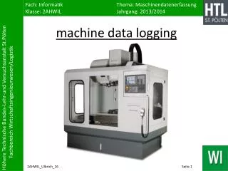
What you need for saving data on the RoboRIO Code that reads the data Writes the data to disk Move data from RoboRIO to processing system
Moving Data from the RoboRIO Use FTP to transfer the file back to the driver station after the match is concluded We create a batch file that does this This batch file is in the same folder destination where the data is to go The batch file renames the file to include the date and time in the file name
Data Transfer Batch File # GetLogging.bat file cd C:\FIRSTrobotics\RA14_LogFileArchive\2014_HomeComing ftp -A -s:ftpcmds.txt 10.17.44.2 for /f "tokens=1-3 delims=/- " %%a in ('date /t') do set XDate=%%a-%%b-%%c for /f "tokens=1-2 delims=: " %%a in ('time /t') do set XTime=%%a.%%b rename "config.txt" "config-%XDate%-%XTime%.txt" rename "logging.csv" "logging-%XDate%-%XTime%.csv" # ftpcmds.txt file get logging.csv get config.txt bye
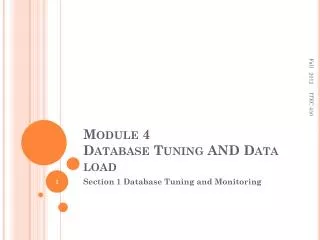
Analyzing the Data • Import into a spread sheet program • Create specialized evaluation program • Moving data from capture device to evaluation device • Archiving data into a subversion repository
??? Questions ??? These are the steps to getting the data from the robot to a graph. Are there any questions about this process before we move on?
PID Tuning Process • Need method to command a step response • Easy ability to change PID gain values
Step Response • One must be able to command an immediate change to a different value • This should be done in a very controlled and precise manner • Essentially the command to the system should be a few cycles of square wave • This can be as simple as a button for the user to press, or as complex as an automation sequence
Step Response We usually just add a button for testing and have the user command the change
Easy Method to change PID gain values Setup a configuration file on the RoboRIO Include in that configuration file the 3 gain values Develop a simple procedure to apply a changed configuration file to the system
Configuration Code Config.h Config.cpp config.txt putconfig.bat ftpcmds.txt
Config File Initialization void Tshirt::RobotInit() { //Start robot cout << "Starting up..." << endl; cout<<"Loading Config File..... "<<endl; Config::LoadFromFile("config.txt"); cout<<"Done!"<<endl;
Questions We now have in place all we need to be able to easily change the PID gain variables Are there any questions at this point?
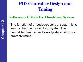
PID Tuning Strategies Iteration by experience Ziegler-Nichols and other tuning strategies Several are mentioned on Chief Delphi http://www.chiefdelphi.com/forums/portal.php PID without a PhD by Tim Wescott
Iteration by Experience After doing this for a while you will get to recognize different patterns and what will correct them P will make slower oscillations D will make fast high frequency oscillations I helps reach the target Not very scientific Can take really long time to find a solution
Start with P Tuning Process For small, low torque motors with little or no gearing, one procedure you can use to get a good baseline tune is to probe it’s response to a disturbance. To tune a PID use the following steps: 1. Set all gains to zero. 2. Increase the P gain until the response to a disturbance is a steady oscillation. 3. Increase the D gain until the oscillations go away (i.e. it’s critically damped). 4. Repeat steps 2 and 3 until increasing the D gain does not stop the oscillations. 5. Set P and D to the last stable values. 6. Increase the I gain until it brings you to the set point with the number of oscillations desired (normally zero but a quicker response can be had if you don’t mind a couple oscillations of overshoot) What disturbance you use depends on the mechanism the control is attached to. Normally moving the mechanism by hand away from the set point and letting go is enough. If the oscillations grow bigger and bigger then you need to reduce the P gain. If you set the D gain too high the system will begin to chatter (vibrate at a higher frequency than the P gain oscillations). If this happens, reduce the D gain until it stops.
Start with D Tuning Process To tune a PID use the following steps: 1. Set all gains to 0. 2. Increase Kd until the system oscillates. 3. Reduce Kd by a factor of 2-4. 4. Set Kp to about 1% of Kd. 5. Increase Kp until oscillations start. 6. Decrease Kp by a factor of 2-4. 7. Set Ki to about 1% of Kp. 8. Increase Ki until oscillations start. 9. Decrease Ki by a factor of 2-4.
Ziegler-Nichols & Other Tuning Strategies Set one of the variables to where the system just oscillates Measure the time period of the oscillation Calculate the PID values from some formula or look up table based on these measurements
Ziegler-Nichols The Ziegler–Nichols tuning method is a heuristic method of tuning a PID controller. It was developed by John G. Ziegler and Nathaniel B. Nichols. It is performed by setting the I (integral) and D (derivative) gains to zero. The "P" (proportional) gain, KP is then increased (from zero) until it reaches the ultimate gain KU , at which the output of the control loop oscillates with a constant amplitude. KU and the oscillation period TU are used to set the P, I, and D gains depending on the type of controller used. Use the table to determine the final gains.
Ziegler-Nichols & Others – Links 1. Ziegler-Nichols Method http://en.wikipedia.org/wiki/Ziegler%E2%80%93Nichols_method 2. Tyreus-Luyben Tuning http://www.chem.mtu.edu/~tbco/cm416/zn.html 3. Comparison of PID Controller Tuning Methods by Mohammad Shahrokhi and Alireza Zomorrodi
Questions? Are there any questions regarding tuning methods?
Steering System Example • Position control for an Ackermann steering mechanism • http://en.wikipedia.org/wiki/Ackermann_steering_geometry • Servo style motor control • Joystick position translates to steer angle
First Pass at Tuning P = .125 I = .001 D = .00125
Second Pass at Tuning P = .220 I = .005 D = .320
Third Pass at Tuning P = .220 I = .005 D = .300
Launching Mechanism Example • Position control for a Leonardo Da Vinci cam mechanism • Reflective index sensor for homing each cycle • Schmitt trigger (7414) for optical sensor • http://www.digikey.com/product-detail/en/SN7414N/296-33604-5-ND/1575159 • http://www.ti.com/lit/ds/symlink/sn7414.pdf
De Vinci Cam Red Alert Cam