Download
1 / 17
180 likes | 197 Vues
This document describes the power and signal interface specifications for a spacecraft, including power service characteristics, load characteristics, signal characteristics, timing interface, command and telemetry interfaces, thermistor and sun pulse interfaces, connectors and harnessing details. Compliance with set regulations and standards ensures smooth and seamless operation of the spacecraft systems.

E N D
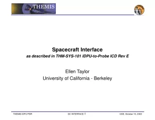
Spacecraft Interface • as described in THM-SYS-101 IDPU-to-Probe ICD Rev E • Ellen Taylor • University of California - Berkeley
Power Service Characteristics • Probe +28V Service Characteristics • Services: Two separately switched services (IDPU and Actuator Interface) • Regulation: 28 +/-6 V • Ripple: function of frequency, defined in ICD figure • Transients: less than +/- 2 Volts for 1 msec on supply lines • Current Limits: Act like circuit breakers, require ground-commanded reset and including an override capability, shall not trip on transients less than 100ms in duration, negative currents, or by the in-rush current specified • Current Monitors: On each instrument power service and included in the spacecraft State of Health telemetry • Returns: Separate return line for each service • Harness: Service and return lines twisted pairs of #22 AWG wire, shielded, connected to spacecraft chassis ground at the signal source end • Impedance: < 500 milliohms DC-10KHz effective line impedance in the service at the instrument connector
Power Load Characteristics • IDPU +28V Load Characteristics • Service: Supplies core IDPU and instrument electronics • Grounding: 28V service load shall return its current through the provided return line. The 28V return shall be isolated from signal and chassis ground by at least 1 Mohm and no more than 1F. • Inrush and Transients: <10A for 1 msec; < Peak power consumption after 10ms • Current Ripple: Current ripple defined in ICD figure • Power Consumption: Power consumption per THM-SYS-009 (by mode) • Actuator +28V Load Characteristics • Service: Supplies transient actuator loads for boom deployment (EFI Spin Plane Boom (SPB) Motors and Mag Boom Actuators) • Inrush and Transients: <10A for 1 msec; < Peak power consumption after 10ms • Current Ripple: TBD • Power Consumption: Power consumption per THM-SYS-009
Signal Interface • Signal Characteristics • RS-422 Interface as shown in Figure 4-2 • Figure 4-2: RS-422 Interface
Timing Interface • Timing Interface • 8MHz Clock: Square wave at 2^23Hz (F8MHZ= 8,388,608 Hz), based on the stable spacecraft clock • 1Hz Pulse: Pulse occurring once per second, based on the stable spacecraft clock as described in Figure 4-3. • Figure 4-3: Clock Signal Timing
Command and TLM Interface • Command and Low Speed Telemetry Interface • Serial command interface used to send data from the spacecraft to the IDPU • Serial telemetry interface used to send status, housekeeping and FGM data from the IDPU to the spacecraft • Transmitted on single serial lines (one for command, one for telemetry) using UART encoding, and differential interface • Data transmitted at 38.4k baud, with 1 start bit (asserted low), 8 data bits, 1 parity bit (even), and one stop bit (active high) per 8-bit byte transmitted, as shown in Figure 4‑4 • Figure 4‑4: Low Speed Command and Telemetry Interface
High Speed TLM Interface • High Speed Telemetry Interface • Bit serial interface used to send full CCSDS telemetry frames from the IDPU to the spacecraft Bus Avionics Unit (BAU). Characteristics and Timing in Figure 4-5. • Figure 4‑5: High Speed Telemetry Interface
Thermistor and Sun Interface • Thermistor Interfaces • One passive thermistor interface will be conditioned, converted, and telemetered by probe • IDPU monitors the temperatures of the rest of the instrument systems when it is powered on • Yellow Springs YSI44908 (311P18-08S7R6). • Sun Pulse Interface • Provided to the IDPU once per spin, indicating the sun crossing. • Single ended • More definition required • Figure 4‑6: Sun Pulse Interface
Pin Signal Harness Pin 1 Signal Actuator 28V #22 TSPN w/ 6 Harness 2 1 IDPU Switched 28V Actuator 28V #22 TSPN w/ 6 #22 TSPN w/ 7 2 3 IDPU Switched 28V Actuator 28V #22 TSPN w/ 7 #22 TSPN w/ 8 3 4 Unused IDPU Switched 28V #22 TSPN w/ 8 4 5 Unused IDPU Thermistor #24 6 5 Actuator 28V Return IDPU Thermistor Return #22 TSPN w/ 1 #24 7 6 IDPU 28V Return Actuator 28V Return #22 TSPN w/ 2 #22 TSPN w/ 1 8 7 IDPU 28V Return Actuator 28V Return #22 TSPN w/ 2 #22 TSPN w/ 3 9 8 IDPU 28V Return Unused #22 TSPN w/ 3 9 Unused Connectors • Connectors & Harnessing • GSFC type S-311-P-4 or equivalent • IDPU-J101 9-pin normal density male D connector on LVPS box • IDPU-J201 9-pin normal density female D connector on PCB front panel Table 4‑1: Connector IDPU-J101 Pinout Table 4‑2: Connector IDPU-J201 Pinout TSPN is a twisted-shielded pair with shield not connected (at this end). TSPS is a twisted shielded pair with shield terminated on the connector backshell (if backshell is used).
Connectors • Connectors & Harnessing • GSFC type S-311-P-4 or equivalent • IDPU-J101 25-pin normal density male D connector on DCB front panel Table 4‑3: Connector IDPU-J301 Pinout TSPN is a twisted-shielded pair with shield not connected (at this end). TSPS is a twisted shielded pair with shield terminated on the connector backshell (if backshell is used).
Command Data Interchange • Command Interface • Periodic synchronization command once per second containing a fixed size block of data • Transmission starts between 0ms and 100ms after the 1Hz Clock pulse, and completes in no more than 500 ms • Includes a spacecraft status segment and a command segment • The command block format is detailed in Table 4‑4 • Table 4‑4: Command Block Format
Spacecraft Status Segment • Spacecraft Status Segment • Includes information on the status of the spacecraft bus, generated automatically on board by the spacecraft processor • Format shown in Table 4‑5 • Table 4‑5: Spacecraft Status Segment Format • Time • Spacecraft clock time in UTC (4 bytes plus 2 bytes of sub seconds) at the time of the next 1Hz clock tick • Ordered MSB first • Status Field • Consists of 8 bytes of data indicating Spacecraft status to the IDPU • Complete definition of the Status field is still TBD
Command Segment • Command Segment • Contains instrument real-time command packets received by the probe in the previous second and time-tagged commands that were scheduled for execution in the previous second • The probe shall copy all instrument command packets into buffer sequentially, with the unused portion at the end being filled with the TBD fill data pattern • Instrument commands are identified by having APIDs over 400 Hex. • Commands limited to 1000 bytes in length • If buffer gets full, unsent commands are lost and an error is reported in the probe telemetry • Only full commands shall be included in the Command Segment, no partial commands • The probe forwards command packets to the IDPU with the format described in the ICD
Telemetry Data Interchange • Low Speed Telemetry Interface • Fixed-size “Housekeeping Telemetry Block” of data once per second • Transmission starts between 0ms and 100ms after the 1Hz Clock pulse, and completes in no more than 500ms • Includes an Instrument State of Health (SOH) packet and a Flux Gate Magnetometer (FGM) packet • Format is detailed in Table 4‑8 • Table 4‑8: Housekeeping Telemetry Block Format
Telemetry Data Interchange • State Of Health Packet • Includes essential engineering data which the probe stores and includes in its telemetry stream • Format of the SOH packet is described in ICD • Format • Flux Gate Magnetometer Packet • Includes engineering data from the Instrument’s Flux Gate Magnetometer used for Probe Attitude Determination • Format of the FGM packet is described in ICD • Length • High Speed Telemetry Interface • The high-speed telemetry interface shall be used to transfer CCSDS-formatted instrument telemetry frames as described in THM-SYS-115 THEMIS Telemetry Format Specification
Mechanical Interface • Interface Drawing • Mechanical configuration provided in the IDPU ICD Drawing shown in IDPU Mechanical Presentation • Details envelope, mounting, and connector locations, CG location, and coordinates • Mass Properties • Instrument Mass Spreadsheet shows the instrument mass properties, including current best estimate and maximum (with reserve) • FOV and Alignment • The IDPU VME chassis requires no FOV or special alignment
Thermal Interface • Thermal Design • Addresses radiative and conductive heat transfer between the IDPU and Probe • Thermal Design Responsibilities • UCB delivers the IDPU thermal model to Swales for inclusion in the top-level spacecraft thermal model. Swales verifies thermal design meets the instrument thermal constraints for all expected spacecraft configurations • Thermal Information provided in ICD (shown previously) • Surface Properties and Thermal Conduction • IDPU Power Dissipation • Heater Requirements (none) • Temperature Requirements