Download
1 / 40
400 likes | 428 Vues
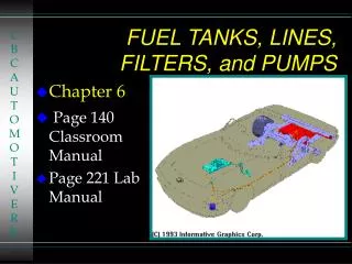
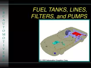
77. FUEL PUMPS, LINES, AND FILTERS. Figure 77-1 A typical fuel tank installation. Figure 77-2 A three-piece filler tube assembly. The main three parts include the upper neck, hose, and lower neck.

E N D
77 FUEL PUMPS, LINES, AND FILTERS
Figure 77-2 A three-piece filler tube assembly. The main three parts include the upper neck, hose, and lower neck.
Figure 77-3 A view of a typical filler tube with the fuel tank removed. Notice the ground strap used to help prevent the buildup of static electricity as the fuel flows into the plastic tank. The check ball looks exactly like a ping-pong ball.
Figure 77-4 Vehicles equipped with onboard refueling vapor recovery usually have a reduced-size fill tube.
Figure 77-5 The fuel pickup tube is part of the fuel sender and pump assembly.
Figure 77-6 On some vehicles equipped with an airflow sensor, a switch is used to energize the fuel pump. In the event of a collision, the switch opens and the fuel flow stops.
Figure 77-7 Ford uses an inertia switch to turn off the electric fuel pump in an accident.
Figure 77-8 Fuel lines are routed along the frame or body and secured with clips.
Figure 77-9 Some Ford metal line connections use springlocks and O-rings.
FREQUENTLY ASKED QUESTION: Just How Much Fuel Is Recirculated? Approximately 80% of the available fuel-pump volume is released to the fuel tank through the fuel pressure regulator at idle speed. As an example, a passenger vehicle cruising down the road at 60 mph gets 30 mpg. With a typical return-style fuel system pumping about 30 gallons per hour from the tank, it would therefore burn 2 gallons per hour, and return about 28 gallons per hour to the tank!
Figure 77-10 Ford spring-lock connectors require a special tool for disassembly.
FREQUENTLY ASKED QUESTION: How Can an Electric Pump Work Inside a Gas Tank and Not Cause a Fire? Even though fuel fills the entire pump, no burnable mixture exists inside the pump because there is no air and no danger of commutator brush arcing, igniting the fuel.
Figure 77-13 The pumping action of an impeller or rotary vane pump.
Figure 77-14 An exploded view of a gerotor electric fuel pump.
Figure 77-15 A cutaway view of a typical two-stage turbine electric fuel pump.
FREQUENTLY ASKED QUESTION: Why Are Many Fuel-Pump Modules Spring-Loaded? Fuel modules that contain the fuel pickup sock, fuel pump, and fuel level sensor are often spring-loaded when fitted to a plastic fuel tank. The plastic material shrinks when cold and expands when hot, so having the fuel module spring-loaded ensures that the fuel pickup sock will always be the same distance from the bottom of the tank. - SEE FIGURE 77–16 .
Figure 77-16 A typical fuel-pump module assembly, which includes the pickup strainer and fuel pump, as well as the fuelpressure sensor and fuel level sensing unit.
Figure 77-17 A schematic showing that an inertia switch is connected in series between the fuel-pump relay and the fuel pump.
Figure 77-18 A typical fuel pulsator used mostly with roller vane-type pumps to help even out the pulsation in pressure that can cause noise.
Figure 77-19 Inline fuel filters are usually attached to the fuel line with screw clamps or threaded connections. The fuel filter must be installed in the proper direction or a restricted fuel flow can result.
Figure 77-20 The final filter, also called a filter basket, is the last filter in the fuel system.
TECH TIP: Be Sure That the Fuel Filter Is Installed Correctly The fuel filter has flow direction and if it is installed backwards, the vehicle will most likely have a restricted exhaust (low power at higher engine speeds and loads). All injectors, throttle body or port, are fitted with one or more filter screens or strainers to remove any particles (generally 10 microns or 0.00039 in.) that might have passed through the other filters. These screens, which surround the fuel inlet, are on the side of throttle-body injectors and are inserted in the top of port injectors. - SEE FIGURE 77–20 .
Figure 77-21 (a) A funnel helps in hearing if the electric fuel pump inside the gas tank is working.
Figure 77-21 (b) If the pump is not running, check the wiring and current flow before going through the process of dropping the fuel tank to remove the pump.
TECH TIP: The Ear Test No, this is not a test of your hearing, but rather using your ear to check that the electric fuel pump is operating. The electric fuel pump inside the fuel tank is often difficult to hear running, especially in a noisy shop environment. A commonly used trick to better hear the pump is to use a funnel in the fuel filter neck. - SEE FIGURE 77–21 .
Figure 77-22 The Schrader valve on this General Motors 3800 V-6 is located next to the fuel-pressure regulator.
TECH TIP: The Rubber Mallet Trick Often a no-start condition is due to an inoperative electric fuel pump. A common trick is to tap on the bottom of the fuel tank with a rubber mallet in an attempt to jar the pump motor enough to work. Instead of pushing a vehicle into the shop, simply tap on the fuel tank and attempt to start the engine. This is not a repair, but rather a confirmation that the fuel pump does indeed require replacement.
Figure 77-23 The fuel system should hold pressure if the system is leak free.
Figure 77-24 If the vacuum hose is removed from the fuelpressure regulator when the engine is running, the fuel pressure should increase. If it does not increase, then the fuel pump is not capable of supplying adequate pressure or the fuel-pressure regulator is defective. If gasoline is visible in the vacuum hose, the regulator is leaking and should be replaced.
TECH TIP: The Fuel-Pressure Stethoscope Test When the fuel pump is energized and the engine is not running, fuel should be heard flowing back to the fuel tank at the outlet of the fuel-pressure regulator. - SEE FIGURE 77–25 . If fuel is heard flowing through the return line, the fuel-pump pressure is higher than the regulator pressure. If no sound of fuel is heard, either the fuel pump or the fuel-pressure regulator is at fault.
Figure 77-25 Fuel should be heard returning to the fuel tank at the fuel return line if the fuel pump and fuel-pressure regulator are functioning correctly.
Figure 77-26 A fuel-pressure reading does not confirm that there is enough fuel volume for the engine to operate correctly.
Figure 77-27 A fuel system tester connected in series in the fuel system so all of the fuel used flows through the meter which displays the rate-of-flow and the fuel pressure.
TECH TIP: Quick and Easy Fuel Volume Test Testing for pump volume involves using a specialized tester or a fuel-pressure gauge equipped with a hose to allow the fuel to be drawn from the system into a container with volume markings to allow for a volume measurement. This test can be hazardous because of flammable gasoline vapors. An alternative test involves connecting a fuel-pressure gauge to the system with the following steps: STEP 1 Start the engine and observe the fuel-pressure gauge. The reading should be within factory specifications (typically between 35 PSI and 45 PSI). STEP 2 Remove the hose from the fuel-pressure regulator. The pressure should increase if the system uses a demand-type regulator.STEP 3 Rapidly accelerate the engine while watching the fuel-pressure gauge. If the fuel volume is okay, the fuel pressure should not drop more than 2 PSI. If the fuel pressure drops more than 2 PSI, replace the fuel filter and retest. STEP 4 After replacing the fuel filter, accelerate the engine and observe the pressure gauge. If the pressure drops more than 2 PSI, replace the fuel pump.
Figure 77-28 A fuel system tester connected in series in the fuel system so all of the fuel used flows through the meter which displays the rate-of-flow and the fuel pressure.
TECH TIP: Remove the Bed to Save Time? The electric fuel pump is easier to replace on many General Motors pickup trucks if the bed is removed. Access to the top of the fuel tank, where the access hole is located, for the removal of the fuel tank sender unit and pump is restricted by the bottom of the pickup truck bed. Rather than drop the tank, it is often much easier to use an engine hoist or a couple of other technicians to lift the bed from the frame after removing only a few fasteners. - SEE FIGURE 77–28 . CAUTION: Be sure to clean around the fuel pump opening so that dirt or debris does not enter the tank when the fuel pump is removed.
Figure 77-29 Hookup for testing fuel-pump current draw on any vehicle equipped with a fuel-pump relay.