Download
1 / 18
190 likes | 293 Vues
Explore the world of rigid origami with a simulation system allowing continuous transformation of 3D origami structures and design creation from crease patterns. The software offers real-time calculations of kinematics, local collision avoidance, and more. Developed by Tomohiro Tachi at The University of Tokyo. For more details, visit http://www.tsg.ne.jp/TT/software/.

E N D
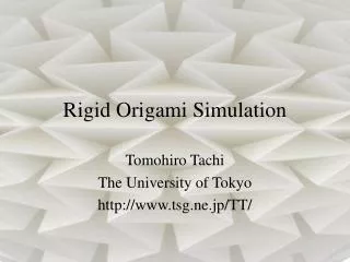
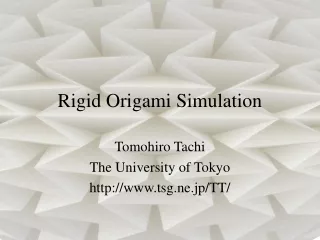
Rigid Origami Simulation Tomohiro Tachi The University of Tokyo http://www.tsg.ne.jp/TT/
About this presentation For details, please refer to • Tomohiro Tachi, "Simulation of Rigid Origami" in Origami^4 : proceedings of 4OSME (to appear)
1 Introduction
Rigid Origami? • rigid panels + hinges • simulates 3 dimensional continuous transformation of origami • →engineering application: deployable structure, foldable structure
Rigid Origami Simulator • Simulation system for origami from general crease pattern. • 3 dimensional and continuous transformation of origami • Designing origami structure from crease pattern.
Software and galleries Software is available: http://www.tsg.ne.jp/TT/software/ flickr:tactom YouTube:tactom
2 Kinematics Single-vertex model Constraints Kinematics
r 2 r 3 l 2 l 3 r 1 l 1 l 4 r 4 Model • Rigid origami model (rigid panel + hinge) • Origami configuration is represented by fold angles denoted as r between adjacent panels. • The configuration changes according to the mountain and valley assignment of fold lines. • The movement of panels are constrained around each vertex.
r C ( ) 2 2 r C ( ) 3 3 B l 2 23 B 12 l 3 r C ( ) 1 1 l B 1 34 B 41 l 4 r C ( ) 4 4 Constraints of Single Vertex • single vertex rigid origami[Belcastro & Hull 2001] • equations represented by 3x3 rotating matrix
Derivative of the equation 3x3=9 equations for each vertex F is orthogonal matrix: 3 of 9 equations are independent (6 is redundant)
r 2 r 3 l 2 l 3 r 1 l 1 l 4 r 4 3 independent equations Derivative of orthogonal matrix F at F=I is skew-symmetric.Let denote direction cosine of li, then
Constraints matrix constraints around vertex kis, For the entire model,
Constraints of multi-vertex (general) origami single vertex: M vertex model: Iff N>rank(C), the model transforms, and the degree of freedom is N- rank(C) (If not singular, rank(C)=3M)
Kinematics Constraints: When the model transforms, the equation has non-trivial solution. represents the velocity of angle change when there are no constraints.
numerical integration Euler integration >Accumulation of numeric error • Use residual of F corresponding to the global matrix elements.
Euler Integration + Newton method Ideal trajectory Euler method + Newton method The solution is, Rawangle change Constrained angle change
3 System
System • Input is 2D crease pattern in dxf or opx format • Real-time calculation of kinematics • Conjugate Gradient method • Runs interactively to • Local collision avoidance • penalty force avoids collision between adjacent facets • Implementation • C++, OpenGL, ATLAS • now availablehttp://www.tsg.ne.jp/TT/software/