Using the Open Network Lab
The Open Network Lab (ONL) is a remotely accessible networking lab that provides gigabit routers with configurable hardware packet forwarding and embedded processors. It offers an intuitive GUI for remote configuration, extensive support for traffic monitoring/visualization, and is a valuable resource for the network research community.

Using the Open Network Lab
E N D
Presentation Transcript
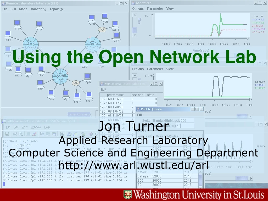
Using the Open Network Lab Jon TurnerApplied Research LaboratoryComputer Science and Engineering Departmenthttp://www.arl.wustl.edu/arl
Motivation • What is ONL? • remotely accessible networking lab • gigabit routers with configurable hardware packet forwarding and embedded processors at each port • routers can be remotely configured through intuitive GUI • extensive support for traffic monitoring/visualization • resource for network research community • Why did we build ONL? • difficult to experiment with high performance routers • commercial routers are not open • open PC routers have limited performance & experiments using them may have limited relevance to high performance routers • net research community needs better experimental resources • What can you do with ONL? • evaluate new and existing protocols & apps in realistic testbed • add new features to routers (embedded processors, hw mods) • mount compelling demonstrations using real-time visualization
Sample ONL Session Bandwidth Usage Network Configuration Routing Tables Queue Length Queue Parameters
3 GigabitEthernetSwitch 16 3 3 3 3 GigE GigE 3 NetworkConfigurationSwitch GigE GigE 3 3 4 ONL Lab Overview • Gigabit routers. • easily configured thru Remote Lab Interface • embedded processors for adding new features • PCs serve as hosts. • half on shared subnets • Net configuration switch. • link routers in virtual topologies • traffic generation • Tools for configuration and collecting results. • monitoring traffic • data capture and playback • Open source • all hw & sw sources on web
ExtensibleRouter User Target Web Site Attacker Mitigating Denial of Service Attacks Users requestconnections to communicate with web site Requires temporary entry in table of partial connections Partial Conn. Table ShadowTable Extensible router observes partial connections and clears those that don’t complete Table fills up blocking legitimate users. Attackers repeatedly start connection process but don’t complete it.
Attack Mitigation Displays Conn. Table fills when plugin off Table clears when plugin on Image xfer blocked Image xfer resumes
People Who Make it Happen Charlie Wisemanweb site dev.dist. sched. Ken WongLab administrationWeb site manager Jyoti ParwatikarRLI software development Stephen Levineplugin development John DehartFPX hardwareSystem integration Fred KuhnsSPC softwareFPX hardware
PP SPC ATMSwitchCore pluginenv. SPC FPX CP PP FPX externallinks . . . . . . . . . . . . to/fromlinks to/fromswitch core Lookup PP Gigabit Router Architecture • Scalable architecture built around ATM switch core. • core provides 2 Gb/s bandwidth per port (2x speedup) • Port processors (PP) implement packet processing • Field Programmable Port Extender (FPX) implements routine packet processing • Smart Port Card (SPC) hosts programmable extensions • Control Processor (Linux PC) handles configuration • can support routing protocols, OA&M, etc.
Gigabit Router Field Prog. Port Extender Smart Port Card ONL Hardware
ReprogrammableApp. Device(38K logic cells+80 KB SRAM) SRAM(1 MB) SDRAM (128MB) 64 36 SRAM(1 MB) SDRAM (128 MB) 36 64 2 Gb/s 2 Gb/s NetworkInterfaceDevice üýþ üýþ 2 Gb/sinterface 2 Gb/sinterface Field Programmable Port Extender (FPX) • Network Interface Device (NID) routes cells to/from RAD. • Reprogrammable Application Device (RAD) functions: • implements core router functions • Xilinx Virtex 1E family • 38K logic cells (LUT4 + flip flop) • 160 block RAMs, 512 bytes each • Core router functions include • packet classification & route lookup • packet storage manager • queue manager • link queues (datagram, reserved) • per flow SPC queues • virtual output queues to switch • control cell processing • access status & control registers • update route tables, packet filters
SDRAM SDRAM ISAR Packet Storage Manager (includes free space list) OSAR from LC to LC from SW to SW Data Path Discard HeaderPointer Pointer Queue Manager Classification and Route Lookup Header Proc. SRAM Register Set SRAM Control Control Cell Processor Route &FilterUpdates Register Set Updates & Status DQ Status & Rate Control Packet Processing in the FPX
Packet Processing in the FPX • Input/Output Segmentation and Reassembly (ISAR/OSAR) • separate reassembly context for link, SPC and each input port • IP packets extracted and stored in memory “chunks” by PSM • headers passed to “control path” • packets retrieved from memory on output and segmented • Packet Storage Manager (PSM) • stores packets in one of two SDRAMs based on where arriving from • Classification and Route Lookup (CARL) • route lookup (best prefix match) using external SRAM • flow lookup (exact 5-tuple match) using external SRAM • packet classification (general match) using on-chip resources • Queue manager (QM) implements three sets of queues • link queues per-flow and datagram queues using weighted DRR • virtual output queues to switch with controllable output rates • can be adjusted by control process in SPC • SPC queues using weighted DRR • Control Cell Processor (CCP) • access to traffic counters, updates to lookup tables & control registers
RouteTable FlowTable Result Proc. & Priority Resolution Input Demux FilterTable headers bypass Classification and Route Lookup (CARL) • Three lookup tables. • route table for routing datagrams – best prefix • flow table for reserved flows – exact match • filter table for management • (adr prefixes, proto, ports) • Lookup processing. • parallel check of all three • return highest priority primary entry and highest priority auxiliary entry • each filter table entry has assignable priority • all flow entries share same priority, same for routes • Route lookup & flow filters • share off-chip SRAM • limited only by memory size • General filters done on-chip • total of 32
Lookup Contents • Route table – ingress only • output port, Queue Identifier (QID) • packet counter • incremented when entry returned as best match for packet • Flow table (exact match) – both ingress and egress • output port – for ingress • Queue Identifier (QID) – for egress or SPC • packet and byte counters • updated for all matching packets • Filter table (general) – ingress or egress (rate limits) • for highest priority primary filter, returns QID • packet counter incremented only if used • same for highest priority auxiliary filter • If packet matches both primary and auxiliary entries, copy is made.
to SPC SPC pkt. sched. ... res. flow queues ... to switch ... to link link pkt. sched. ... arriving packets datagram queues Queue Manager each queue has WDRR weight and discard threshold 128 flow queues, each with WDRR weight and discard threshold VOQ per output, each with rate and discard threshold 64 datagram queues, each with WDRR weight and discard threshold all queues have a byte length that can be queried
Controlling the Queue Manager • All queues are configurable. • discard threshold • WDRR quota • Virtual Output Queues (QIDs 504-511) • all packets going to switch placed in VOQ for target output • Datagram output queues (QIDs 440-503) • packets going to link with no special queue assignment are hashed to one these 64 queues • Reserved output queues (QIDs 256-439) • SPC queues (QIDs 0-127, 128-255) • assigned in pairs (q, q+128) • packets to SPC use 1-127 • packets returning from SPC, going to link use 128-256
FPX Traffic Counters, Status Info. • Packet and byte counters are read via control cells • returned value includes counter value and timestamp • timestamps used by software to compute rates • Port level packet counters • received from/sent to link (2 counters) • received from/sent to SPC on ingress/egress side (4 counters) • received from/sent to router input/output ports (16 counters) • Packet drop counters • ISAR dropped cell counter • ISAR invalid packet counter (CRC failure, etc.) • QM dropped packet for link queues, switch queues, SPC queues • And many others,
Selected FPX Counters 00 packets from link 04 packets from ingress port 0 05 packets from ingress port 1 . . . 11 packets from ingress port 7 12 ingress-side packets from SPC 13 egress-side packets from SPC 16 packets to link 20 packets to egress port 0 . . . 27 packets to egress port 7 28 ingress-side packets to SPC 29 egress-side packets to SPC 64 ISAR input cell drops 65 ISAR invalid packet drops 66 QM packet drops for link 67 QM packet drops for switch 68 QM packet drops for SPC
Smart Port Card 128 MB Pentium NorthBridge Cache FlashDisk PCI APIC FPGA • FPGA routes data straight-thru or to/from SPC. • 2 Gb/s data paths • APIC is Network Interface Chip • segments packets into cells on transmission • reassembles in memory on reception • 500 MHz Pentium III processor • 100 MHz EDO memory • 32 bit PCI at 33 MHz • flash disk • standard BIOS • Hosts software plugins • options processing • application-specificprocessing
VXT RSQ RCB XMB OPP CYCB IPP Cell Buffer . . . OXBAR IXBAR . . . VXT RSQ RCB XMB OPP CYCB IPP Core ATM Switch 4 ParallelSwitch Planeseach cell split into 4 pieces ResequencingBuffer RecyclingBuffer Virtual Circuit/Path Lookup Table Dual PriorityTransmit Buffer
FPX FPX FPX FPX FPX FPX FPX FPX FPX FPX FPX FPX FPX FPX FPX FPX PVCs for Inter-port Traffic VCI remapping packets from input k received on VCI 64+k packets to output k sent on VCI 64+k • Permanent Virtual Circuits carry traffic between FPXs. • Egress FPX maintains separate reassembly buffers. • Can use cell counters in switch to monitor traffic. • Port-level cell counters also available.
Switch Congestion • Causes • switch provides bandwidth of about 2 Gb/s per port • so, possible for multiple inputs to overload an output causing congestion in switch and lost packets • problem can be exacerbated by fragmentation effects • Distributed scheduling • distributed scheduler controls VOQ rates to prevent congestion • implemented by SPC-resident software modules • run periodically (every 500 ms) • exchange information on VOQ backlogs, output backlogs • adjusts VOQ rate controls in FPX • Manual operation • distributed scheduling can be turned off • gives user direct control over input VOQ rates • makes it possible to overload switch, so use carefully
1 1 DS to output 1 . . . Core Switch to output n 2 2 . . . . . . n n Distributed Scheduling schedulers exchangeperiodic status reports scheduler pacesqueues to avoid overload and avoid underflow • Coarse-grained nature of scheduling makes it scalable. virtual output queues
Scheduling Algorithm Sketch • Goals: avoid switch congestion and output queue underflow (work-conservation). • Backlog proportional sharing. • if input accounts for 30% of input-side backlog to output j, it is allocated 30% of switch bandwidth to output j • Least occupied output first. • each input sends its allocated amount to output with shortest queue • as much as it can to output with second smallest queue, etc. • continue until all input bandwidth is allocated • Refinements. • add small offset to actual VOQ sizes and use these adjusted VOQ sizes for backlog-proportional sharing • second pass to assign otherwise “wasted” input side bandwidth • allows packets to flow to previously idle outputs more quickly • Approximates centralized work-conserving scheduler.
phase 0 phase 1 phase 2 phase 3 Stress Test • Inputs combine to build backlogs for outputs 0, 2, 4,... • creates input contention • As inputs “drop out” they switch to unique output. • must supply unique output, while clearing backlogs • If speedup too small, output queues run dry early. • Stress test can have p phases, k steps per phase • ideal output-queued switch can forward all data in pk steps. • evaluate scheduler based on its “overshoot” • Best off-line schedulers require speedup of at least 1.5 for zero overshoot on 16 phase test, with 1 step per phase.
Sample Stress Test Performance idealfinishtime overshoot15% • Scaled down to stretch time scale. • 20 Mb/s link rate • S=1.25 • 4 phases • 3 second phase time
Internet netBSD serversfor plugin prep onl server control subnet onlBSD1,2 onl03 usr CP CP CP CP 16 2 3 3 2 2 2 3 3 GE GE GE GE 2,3 2,3 2,3 2,3 0 0 0 0 1 1 1 1 192.160.2.* 4-7 192.160.1.* 4-7 4-7 192.160.3.* 4-7 192.160.4.* NSP3 NSP2 NSP4 NSP1 configuration switch Testbed Organization
Internet netBSD serversfor plugin prep onl server control subnet onlBSD1,2 onl03 usr CP CP CP CP 16 2 3 2 2 3 3 2 3 GE GE GE GE 2,3 2,3 2,3 2,3 0 0 0 0 1 1 1 1 192.160.2.* 4-7 192.160.1.* 4-7 4-7 192.160.3.* 4-7 192.160.4.* NSP3 NSP4 NSP2 NSP1 configuration switch Major Software Components SSH proxy switch controller and SPC control message handler ONL daemon Remote Lab Interface (RLI) SSH tunnel
Getting Started onl.arl.wustl.edu or onl.wustl.edu tutorial get an account
After Logging in download Remote Lab Interface Software • extra links • getting started • status • reservations install Java runtime environment configure SSH tunnels
SSH Tunnel Configuration Name=onl, ports 7070, type=TCP
Configuring Topology Add hosts can as needed. Drag graphic elements to prettify display. Cluster includes router, GE switch and fixed set of hosts Port 0 used for Control Processor. Spin handle rotates ports.
Configuring Topology (cont.) Add links as needed. These are implemented using configuration switch. Select “Commit” item to transfer configuration changes to hardware. Note: first time is slow.
Configuring Topology (cont.) Note color change following commit. Indicates RLI connected to lab hw. Save config. to a file for use in later session. Right-click on host to get host name and IP address. n2p2 is local symbolic name192.168.2.48 is local IP addressonl02.arl.wustl.edu is external name
Verifying Host Configuration ssh to host of interest from onl03 ifconfig atm0 displays info on host’s ATM interfaces (used by directly connected hosts) Verify that IP address of interface matches displayed address.
Configuring Routes Generate default routes to enable communication. Entry defined by address prefix and mask. Specifies router output port. Click on port to access route table (and other stuff). To reach other router use port 6.
192.168.1.16/28 0192.168.1.32/28 1192.168.1.48/28 2192.168.1.64/28 3192.168.1.80/28 4192.168.1.96/28 5192.168.2.0/24 6 192.168=c0.a8 0000 00 01 1 0 0 6 1 0 RouteTable 1 1 0 0 FlowTable 0 1 0 1 0 1 Result Proc. & Priority Resolution Input Demux 3 5 1 2 0 4 FilterTable headers bypass What does This Mean for Router? Route table implemented using space-efficient variant of multibit trie.
Verifying Routes secure shell session to onl02.arl.wustl.edu ping packets passing through ONL routers
Monitoring Traffic select polling rate select desired monitor variable specify monitoring view peak per ping packet ping traffic
Adding More Data click on labels to change text forward and return traffic
Changing Routes note effect of route change route traffic through bottom link
Using Flow Tables (Exact Match) add filter traffic switches back to top link port numbers ignored for ICMP enter 1 for protocol (ICMP) select ingress filter tables for port 2 specifies top link priority allows flow table entry to override route
Using General Filter Tables traffic switches back to bottom priority allows filter table entry to override flow table entry protocols and ranges may be “don’t-care” addresses may be specified as prefixes specifies bottom link
Using Auxiliary Filter to Copy Flow double the return traffic forward traffic on both links auxiliary filter replicates data stream
Lab Exercise 1 • Log into ONL web site (as hotI1, hotI2, hotI3, hotI4). • view current reservations, status, download RLI • Run RLI. • open SSH connection to onl03.arl.wustl.edu, configure onl tunnel • setup configuration with one cluster, extra hosts on ports 4,5 and link joining ports 6,7 • generate default routes, commit and save • from onl03, open SSH connection to n1p2 and ping other hosts • Modify routing table and monitor traffic. • monitor traffic going both ways on 6-to-7 link • start ping from n1p2 to n1p3 • re-route all traffic from port 2 to port 6 • re-route all traffic from port 3 to port 7 • commit • Experiment with filters.
Generating Traffic with Iperf available at http://dast.nlanr.net/projects/Iperf/ installed on all onl hosts Sample uses • iperf –s -u • run as UDP server on port 5001 • iperf –c server –u –b 20m –t 300 • run as client sending UDP packets to server at 20 Mb/s for 300 secs. • iperf –s –w 4m • run as TCP server on port 5001 • set max window to 4 MB • iperf –c server –w 4m –t 300 • run as client, sending as fast as possible, with max window 4 MB
single UDP stream onl15 onl02 Using Iperf start UDP sender start UDP receiver
onl28 onl18 onl13 onl14 onl19 onl11 Multiple Iperf Streams received bandwidth sending bandwidth
Iperf Scripts runServers starts iperf servers remotely on specified hosts runClients runs iperf clients in loop with delays to offset start times
Monitoring Separate Flows selectport-to-port bandwidth bandwidths entering and exiting bottleneck link desired output