Download
1 / 28
350 likes | 783 Vues
Echocardiography. Valvular Stenosis. Etiology. Congenital Post Inflammatory Degenerative. The Effects. Increased flow velocity . Increased pressure gradient. Chamber response to pressure overload. Upstream effects. Echocardiographic Evaluation. Etiology of the stenosis

E N D
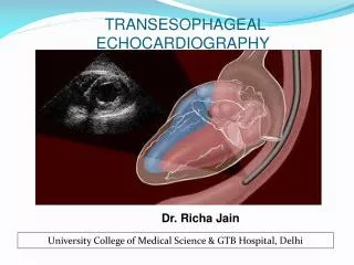
Echocardiography Valvular Stenosis
Etiology • Congenital • Post Inflammatory • Degenerative
The Effects • Increased flow velocity . • Increased pressure gradient. • Chamber response to pressure overload. • Upstream effects
Echocardiographic Evaluation • Etiology of the stenosis • Quantification of stenosis severity • Coexisting valvular lesions
Echocardiographic Evaluation • Assessment of Ventricular systolic function • Response of upstream cardiac structures and pulmonary vascular bed to the chronic pressure overload
Valvular Stenosis Fluid Dynamics
Fluid Dynamics • High-Velocity Jet • Distal Flow Disturbances • Proximal Flow Pattern
High-Velocity Jet • Characterized by formation of a laminar, high velocity jet in the narrowed orifice. • The flow profile at the origin of the jet is blunt. • The jet maintains a blunt profile as it reaches its narrowest cross-sectional area in the vena contracta.
High Velocity Jet • Physiologic orifice (the narrowest CSA of flow) is smaller than the anatomic orifice area. • Discharge coefficient = Physiologic orifice Anatomic orifice
High Velocity Jet • The magnitude of difference between the physiologic and anatomic are depends on the orifice geometry and the Reynolds number.
Pressure Gradient-Velocity Relationship P = ½ (v22 – v12) + (dv/dt)dx + R(v) ½ (v22 – v12) = Convective acceleration (dv/dt)dx = Local acceleration R(v) = Viscous Resistance
Pressure Gradient-Velocity Relationship • DP = pressure gradient across stenosis • r = mass density of blood • V2 = velocity in the stenotic jet
Pressure Gradient-Velocity Relationship • V1 = velocity proximal to stenosis • (dv/dt)dx = time varying velocity at each distance along the flow stream. • R = constant describing viscous losses.
Pressure Gradient-VelocityRelationship • Eliminating the term for viscous losses and acceleration. • Substituting known values for mass density of blood • Adding conversion factor for measuring velocity in m/s and pressure gradient in mmHg, the Bernoulli equation can be reduced to D P = 4 ( v22 – v12)
Pressure Gradient-VelocityRelationship • If the proximal velocity is less than 1m/s as is commonly the case for stenotic valve, it becomes even smaller when squared. • Thus the proximal velocity is often ignored in clinical setting so that: Simplified Bernoulli equation is D P = 4v2
Distal flow Disturbance • Distal to stenosis, the flow stream becomes disorganized with multiple blood flow velocities and direction. • The distance of this flow disturbance is determined by the severity of the stenosis. • The flow disturbance can be used to define the exact anatomic site of the stenosis.
Proximal Flow Patterns • The spatial flow velocity profile proximal to a stenotic valve depends on • Valve anatomy • Inlet geometry • Degree of flow acceleration
Proximal Flow Pattern Aortic Valve/Pulmonic Valve Tapering outflow tract + Acceleration of blood flow by ventricular systole Flat Velocity Profile
Proximal Flow Pattern Calcific aortic Stenosis Small spatial region of flow proximal Acceleration
Proximal Flow Pattern Congenital aortic stenosis Larger region of proximal flow acceleration
Proximal Flow Patterns Mitral/Tricuspid Valve Large inlet chamber + Low pressure gradient – Passive flow Large Proximal Flow Acceleration region
Proximal Flow Pattern This results in a • Curved velocity profile • Flow velocities faster adjacent to and in the center of a line continuous with the jet direction through the narrowed orifice. • Flow velocities slower at increasing radial distances from the valve orifice . • Hemi-elliptical Velocity Profile
PISA Any 3D surface area proximal to a narrowed orifice at which all the blood velocities are equal is called a proximal isovelocity surface area (PISA).