Chemistry 481(01) Spring 2014
621 likes | 1.52k Vues
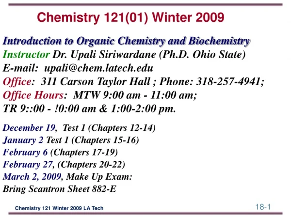
Chemistry 481(01) Spring 2014. Instructor: Dr. Upali Siriwardane e-mail: upali@latech.edu Office: CTH 311 Phone 257-4941 Office Hours: M,W 8:00-9:00 & 11:00-12:00 am; Tu,Th , F 10:00 - 12:00 a.m . April 10 , 2014: Test 1 (Chapters 1, 2, 3,)

Chemistry 481(01) Spring 2014
E N D
Presentation Transcript
Chemistry 481(01) Spring 2014 • Instructor: Dr. Upali Siriwardane • e-mail: upali@latech.edu • Office: CTH 311 Phone 257-4941 • Office Hours: • M,W 8:00-9:00 & 11:00-12:00 am; • Tu,Th, F 10:00 - 12:00 a.m. • April 10 , 2014: Test 1 (Chapters 1, 2, 3,) • May 1, 2014: Test 2 (Chapters 6 & 7) • May 20, 2014: Test 3 (Chapters. 19 & 20) • May 22, Make Up: Comprehensive covering all Chapters
Chapter 20. d-Metal complexes: electronicstructure and properties Electronic structure 473 20.1 Crystal Field theory 473 20.2 Ligand Field theory 483 Electronic spectra 487 20.3 Electronic spectra of atoms 487 20.4 Electronic spectra of complexes 493 20.5 Charge-transfer bands 497 20.6 Selection rules and intensities 499 20.7 Luminescence 501 Magnetism 502 20.8 Cooperative magnetism 502 20.9 Spin crossover complexes 504
Crystal Field theory (CFT) The ligands are viewed simply as mere point charges. One focuses on the valence d orbitals of the central transition metal atom and examines how the relative energies of the d orbitals change upon introduction of external negative point charges (the ligands).
Ligand Field theory (LFT) Direct application of Molecular Orbital (MO) theory using SALC of Ligand Molecular and Metal d orbital directly leads to following diagrams
MO energy levels for an octahedral complex with six ligands [Cr(CO)6]
Electronic Transition in Transition metal Complexes • Transition between metal-centered orbitals with d-character (d-d transition). • Transition between metal- and ligand-centeredMOs which transfer charge from metal to • ligand or ligand to metal.
Charge Transfers (CT) Note: When Charge transfer (CT) give rise to • intense absorptions (), CT absorption bands in electronic spectra are usually broad • whereas d-d bands are much weaker. In some spectra, CT mask bands due to d-d transitions often occurs at higher energies than d-d absorptions. MLCT = metal-to-ligand charge transfer LMCT = ligand-to-metal charge transfer
Electronic Spectra of Transition Metals Why are so many coordination compounds colored, in contrast to most organic compounds? Low energy transitions between different electron configurations. [Co(OH2)6]2+ [CoCl4]2- Pink Blue [Ni(OH2)6]2+ [Ni(NH3)6]2- Green Blue
What causes the change in color of Solution? Electronic Transitions “One-Electron Model” for hydrogen Doesn’t work for electronic spectra Must consider how electrons interact with one another. Quantum Numbers of Multi-electron Atoms Electron configurations are more complicated than we’ve considered so far
Electron-Electron Repulsions Hunds Rule Electron Repulsions result in: Electrons occupying separate orbitals when possible Electrons in separate orbitals have parallel spins Easy to describe individual electrons, more complicated to describe “sets” of electrons. p2, p3, d2, d3, d4, f2, f3,f5 etc
Vector Addition of ml and ms These are obtained by the vectorial addition of the individual electron Orbital Angular Momentum i.e. the ml values and the Spin Angular Momentum i.e. the msvalues Must first ask which order is the vectorial addition to be carried out ? If we consider just 2 electrons in an incomplete shell: Which is the stronger coupling : ms1.ms2 and ml1.ml2 Or ms1.ml1 and ms2.ml2 ? This choice gives rise to 2 coupling schemes : a) Russell-Saunders coupling (RS) b) jj-coupling
Example Consider a Carbon Atom Electron Configuration: 1s2 2s2 2p2 Do the 2-p electrons have the same energy? Three major energy levels for the p2 electron configuration Lowest energy major level is further split into three levels The two electrons in p2 configuration are not independent Orbital angular momenta interact Spin angular momenta interact Russell-Saunders or LS Coupling
Russell-Saunders orLS Coupling • LS Coupling • Interactions produce atomic states called microstates described by new quantum numbers: • ML = SmlTotal orbital angular momentum • Ms = SmsTotal spin angular momentum
Labelling Term Symbols Maximum Values of L = 0, 1, 2, 3, 4 etc… S P D F G etc… cf 1 -electron case (orbitals) Maximum Values of S = 0, 1/2, 1, 11/2, 2 etc… 2S+1 = 1 2 3 4 5 etc… as superscript
How do we determine the Microstates for p2? 1. Determine the possible values of ML and MS. max. ML? 2 values of ML? 2, 1, 0, -1, -2 max. MS? 1 values of Ms? 1, 0, -1 Total Orbital Momentum L 0 1 2 3 4 5 6 S P D F G H I Spin multiplicity 2S+1 = 1 2 3 4 5 The Russell Saunders term symbol that results from these considerations is given by: (2S+1)L
Determine the electron configurations allowed by the Pauli principle. l =1; x=2 Microstates for p2 =15
TERMS SYMBOLS are referred to as singlet, doublet, triplet etc. according to value of 2S+1. Denotes Spin multiplicity or spin degeneracy of term. Thus the terms for p2 can be derived as 1D, 3P, 1S The total degeneracy of each term = (2S+1)(2L+1) Thus the original set of 15 microstates for p2 has become sub divided into 3 terms : 3P 3x3 = 9 1D 1x5 = 5 1S 1x1 = 1 15
d1 configuration As an example, for a d1 configuration: S= + ½, hence (2S+1) = 2 L=2 and the Ground Term is written as 2D d9 has the same configuration
d2 term symbols Nl=2(2l+1) l=2 10!/2!(8!) Microstates for d2 =45 max. ML? 4 values of ML? 4, 3, 2, 1, 0, -1, -2, -3, -4 max. MS? 1 values of Ms? 1, 0, -1 1S 3S1P3P 1D 3D1F3F 1G 3G 1 3 3 9 5 15 7 21 9 27 For d2 terms: 1S 1D 1G 3P 3F; the lowest is 3F 1S 1x1 = 1 3P 3x3 = 9 1D 1x5 = 5 3F 3x7 = 21 1G 1x9 = 9 45 L = 0 1 2 3 4 S P D F G S = 1 3
Spin-Orbit Coupling In the Russell-Sunders coupling scheme after allowing for the coupling of the individual spins to give a resultant spin (S) and the individual orbital angular momenta to give a resultant value (L) then we can consider spin-orbit coupling (J) S.L J (the total angular momentum) The J values are given by: L + S, L + S - 1,…L - S The levels then arising are labeled: 2S+1LJ For example: consider the ground state term 3F for d2 Here S = 1, L = 3; hence J = 4, 3 ,2 3F level into three new closely separated levels 3F4, 3F3, 3F2
Terms for 3dn free ion configurations Note that dn gives the same terms as d10-n
Ground Term Symbol Have the maximum spin multiplicity If there is more than 1 Term with maximum spin multiplicity, then the Ground Term will have the largest value of L.
The Crystal Field Splitting of Russell-Saunders terms Crystal or Ligand Field affect the different orbitals (s, p, d, etc.) will result in splitting into subsets of different energies based on character table. Octahedral (Oh)field environment will cause the d orbitals to split to give t2g and eg subsets of 5 states D term symbol into T2g and Eg(where upper case is used to denote term symbols and lower case orbitals). f orbitals are split to give subsets known as t1g, t2g and a2g subsets of 7 states. F term symbol will split by a crystal field will give states known as T1g,T2g, and A2g.
Selection rules and intensities 1) spin-forbidden, ∆S ≠ 0, transitions are generally much weaker than spin-allowed transitions. f ↔ f, s ↔ d, p ↔ f etc. 2) Laporteselection rule : Must be a change in parity; Allowed transitions: g ↔u Forbidden transitions: g ↔g u ↔ u 3) Δl = ± 1 So, allowed transitions are s ↔ p, p ↔ d, d ↔ f; Forbidden transitions are s ↔ s, p ↔ p, d ↔ d,
Crystal Field Splitting of RS terms in high spin octahedral crystal fields.
Orgel diagrams Diagram showing the terms arising from crystal field splitting The spin multiplicity and the g subscripts are dropped for simplicity right (Oh) d2 , d7 Left (Oh) d3 , d8 (Td) d7
Racah Parameters Racah Parameters In practice, however, two alternative parameters are used for dn terms: B = F2 - 5F4 C = 35F4 These are called Racah Parameters; Racah recognised that these relationships appeared frequently and thus it is more convenient to use B and C.
Term reversal on going dn to d10-n d1 and d92D d2 and d83F and 3P d3 and d74F and 4P d4 and d65D
The transitions responsible for the absorption and luminescence of Cr3+ions in ruby.