Download
1 / 40
400 likes | 512 Vues
3D Sensing and Reconstruction Readings: Ch 12: 12.5-6, Ch 13: 13.1-3, 13.9.4. Perspective Geometry Camera Model Stereo Triangulation 3D Reconstruction by Space Carving. 3D Shape from X means getting 3D coordinates from different methods. shading silhouette texture stereo

E N D
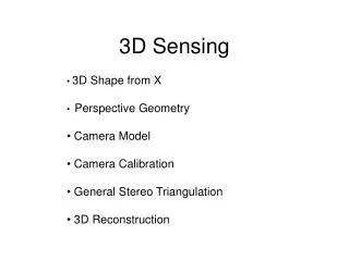
3D Sensing and ReconstructionReadings: Ch 12: 12.5-6, Ch 13: 13.1-3, 13.9.4 • Perspective Geometry • Camera Model • Stereo Triangulation • 3D Reconstruction by Space Carving
3D Shape from Xmeans getting 3D coordinatesfrom different methods • shading • silhouette • texture • stereo • light striping • motion mainly research used in practice
Perspective Imaging Model: 1D real image point This is the axis of the real image plane. E xi f camera lens O is the center of projection. O image of point B in front image D This is the axis of the front image plane, which we use. xf zc xi xc f zc = xc B 3D object point
Perspective in 2D(Simplified) Yc camera P´=(xi,yi,f) Xc 3D object point yi P=(xc,yc,zc) =(xw,yw,zw) ray f F xi yc optical axis zw=zc xi xc f zc = xi = (f/zc)xc yi = (f/zc)yc Zc xc Here camera coordinates equal world coordinates. yi yc f zc =
3D from Stereo 3D point left image right image disparity: the difference in image location of the same 3D point when projected under perspective to two different cameras. d = xleft - xright
Depth Perception from StereoSimple Model: Parallel Optic Axes image plane z Z f camera L xl b baseline f camera R xr x-b X P=(x,z) y-axis is perpendicular to the page. z x-b f xr z x f xl z y y f yl yr = = = =
Resultant Depth Calculation For stereo cameras with parallel optical axes, focal length f, baseline b, corresponding image points (xl,yl) and (xr,yr) with disparity d: This method of determining depth from disparity is called triangulation. z = f*b / (xl - xr) = f*b/d x = xl*z/f or b + xr*z/f y = yl*z/f or yr*z/f
Finding Correspondences • If the correspondence is correct, triangulation works VERY well. • But correspondence finding is not perfectly solved. • (What methods have we studied?) • For some very specific applications, it can be solved • for those specific kind of images, e.g. windshield of • a car. ° °
3 Main Matching Methods 1. Cross correlation using small windows. 2. Symbolic feature matching, usually using segments/corners. 3. Use the newer interest operators, ie. SIFT. dense sparse sparse
Epipolar Geometry Constraint:1. Normal Pair of Images The epipolar plane cuts through the image plane(s) forming 2 epipolar lines. P z1 y1 z2 y2 epipolar plane P1 x P2 C1 C2 b The match for P1 (or P2) in the other image, must lie on the same epipolar line.
Epipolar Geometry:General Case P y1 y2 P2 x2 P1 e2 e1 x1 C1 C2
Constraints 1. Epipolar Constraint: Matching points lie on corresponding epipolar lines. 2. Ordering Constraint: Usually in the same order across the lines. P Q e2 e1 C1 C2
Structured Light light stripe • 3D data can also be derived using • a single camera • a light source that can produce • stripe(s) on the 3D object light source camera
Structured Light3D Computation • 3D data can also be derived using • a single camera • a light source that can produce • stripe(s) on the 3D object 3D point (x, y, z) (0,0,0) light source b x axis f b [x y z] = --------------- [x´ y´ f] f cot - x´ (x´,y´,f) image 3D
Depth from Multiple Light Stripes What are these objects?
Our (former) System4-camera light-striping stereo cameras projector rotation table 3D object
Camera Model: Recall there are 5 Different Frames of Reference yc xc • Object • World • Camera • Real Image • Pixel Image zw yf C xf image a W zc yw pyramid object zp A yp xp xw
The Camera Model How do we get an image point IP from a world point P? Px Py Pz 1 c11 c12 c13 c14 c21 c22 c23c24 c31 c32 c331 s IPr s IPc s = image point world point camera matrix C What’s in C?
The camera model handles the rigid body transformation from world coordinates to camera coordinates plus the perspectivetransformation to image coordinates. 1. CP = T R WP 2. FP = (f) CP Why is there not a scale factor here? CPx CPy CPz 1 s FPx s FPy s FPz s 1 0 0 0 0 1 0 0 0 0 1 0 0 0 1/f 0 = 3D point in camera coordinates image point perspective transformation
Camera Calibration • In order work in 3D, we need to know the parameters • of the particular camera setup. • Solving for the camera parameters is called calibration. yc • intrinsic parameters are • of the camera device • extrinsic parameters are • where the camera sits • in the world yw xc C zc W xw zw
Intrinsic Parameters • principal point (u0,v0) • scale factors (dx,dy) • aspect ratio distortion factor • focal length f • lens distortion factor • (models radial lens distortion) C f (u0,v0)
Extrinsic Parameters • translation parameters • t = [tx ty tz] • rotation matrix r11 r12 r130 r21 r22 r230 r31 r32 r330 0 0 0 1 R = Are there really nine parameters?
Calibration Object The idea is to snap images at different depths and get a lot of 2D-3D point correspondences.
The Tsai Procedure • The Tsai procedure was developed by Roger Tsai • at IBM Research and is most widely used. • Several images are taken of the calibration object • yielding point correspondences at different distances. • Tsai’s algorithm requires n > 5 correspondences • {(xi, yi, zi), (ui, vi)) | i = 1,…,n} • between (real) image points and 3D points. • Lots of details in Chapter 13.
We use the camera parameters of each camera for general stereo. P y1 y2 P2=(r2,c2) x2 P1=(r1,c1) e2 e1 x1 B C
For a correspondence (r1,c1) inimage 1 to (r2,c2) in image 2: 1. Both cameras were calibrated. Both camera matrices are then known. From the two camera equations B and C we get 4 linear equations in 3 unknowns. r1 = (b11 - b31*r1)x + (b12 - b32*r1)y+ (b13-b33*r1)z c1 = (b21 - b31*c1)x + (b22 - b32*c1)y + (b23-b33*c1)z r2 = (c11 - c31*r2)x+ (c12 - c32*r2)y+ (c13 - c33*r2)z c2 = (c21 - c31*c2)x+ (c22 - c32*c2)y + (c23 - c33*c2)z Direct solution uses 3 equations, won’t give reliable results.
Solve by computing the closestapproach of the two skew rays. V = (P1 + a1*u1) – (Q1 + a2*u2) (P1 + a1*u1) – (Q1 + a2*u2) · u1 = 0 (P1 + a1*u1) – (Q1 + a2*u2) · u2 = 0 P1 u1 solve for shortest V P Q1 u2 If the rays intersected perfectly in 3D, the intersection would be P. Instead, we solve for the shortest line segment connecting the two rays and let P be its midpoint.