Download
1 / 65
650 likes | 674 Vues
Learn about different network topologies such as star, ring, bus, and mesh, and understand the principles of packet routing by IP address.

E N D
COMP 1121: Computers and Computer Networks Session 5: Network Topologies and Routing
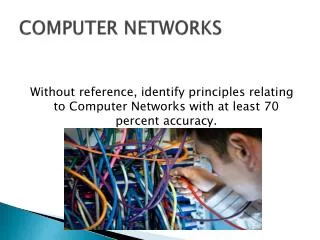
Session Objectives • By the time you have finished this teaching/learning session you should be able to: • List and identify the main network topologies • Explain the basic principles of packet routing by IP address • Explain how ALOHA works as a means of resolving contention between packet streams • Relate IEEE802 standards to topologies and contention resolution types
Network Topologies • Star - central computer with cables radiating out • Ring - ring of cable with computers linked to the ring • Bus - end-to-end cable (backbone) with computers linked to the backbone • Mesh - computers each linked (with cable?) to several other computers
Star Topology Remote client Central server(s) or hub Remote client
Star Topologyfrom http://www.linuxdoc.com/howto/intro_to_networking/index.lxp?lxpwrap=c5434.htm
Star Topology • Used since the very early days of computer networking • Similar to system of connecting a mainframe or midrange computer to dumb terminals • note: the mainframe/dumb terminal scenario is actually a multi-user system, and not a network, because there is only one intelligent device - the central computer
Star Topology (Hubs) server hub
Star Topology (Hubs) • All nodes connected to a common central location, known as a hub • Hubs can link to other secondary hubs, creating subnets • All packets of data transferred through the network go through the main hub • Therefore it must have a high bandwidth
Star Topology (Hubs) • Quite fault tolerant because: • If one network link fails… • only a single node loses connection • However, if the hub itself fails then the whole subnet/network fails!
Ring Topology • no central hub • data from one node: • passes into a “ring” of cabling • travels round the ring • Mechanism: • every node receives all network data • takes the data that is addressed to it • passes the rest back to the ring
Ring Topology • Evaluation • If a node fails or a cable breaks, the whole ring could fail • “monitor stations” are therefore used to quickly detect failures • If data does not find its destination node, it will pass right round the ring until it returns to its originator
Ring wiringimage from http://www.delmar.edu/Courses/ITNW2313/access.htm • Not always a physical ring… • a logical ring may be actually wired as a physical star (opp) • or can even use a physical bus arrangement (next page)
Bus Topology Central Server Remote client Terminator Terminator Remote client
Linear bus topologyfrom http://fcit.usf.edu/network/chap5/chap5.htm
Bus Topology • Once Popular technology for small (<20 computers) networks • T-pieces electrically connect computers to the backbone • Bus carries all network data • All nodes are connected to a single common cable known as the backbone • The backbone is end-to-end, and a terminator is needed at each end to prevent signal bounce and to complete the circuit
Bus Topology • If one node fails, other nodes are not affected • If the backbone cable breaks, the whole network may halt • Removing either of the terminator(s) prevents to flow of data and stops the network • Unfastening a T-piece will disconnect a computer from the network, but the rest of the network will still function
Mesh topology • Each computer on the network is attached to several other computers • Only suitable for peer-peer networks • Uses a lot of cable • Very good for fault tolerance • The Internet is a mesh network
The Internet is a large Mesh Network Over 750 million Server computers! Source: ISC Domain name Survey, online at http://www.isc.org/solutions/survey
Full mesh topologyfrom http://www.cisco.com/warp/public/759/ipj_3-4/ipj_3-4_routers.html
Partial mesh topologyfrom http://www.cisco.com/warp/public/759/ipj_3-4/ipj_3-4_routers.html
Mesh Topology (3) • How many links are needed to connect together 3 nodes in a full mesh? • 4 nodes? • 5 nodes? • 10 nodes? • 1000 nodes?
Routing • Problem: how to get a message from one computer to another • Needs a means of identifying the destination • IP address, or similar • And a means of finding that destination • calculating/choosing a pathway to the destination through the network
Types of routing 1:Broadcast Routing (e.g. Ethernet) • Message is sent to all computers in the subnet • Only the computer to which it is addressed bothers to read its contents • Uses MAC addresses (unique identifier of the NIC, function at OSI layer 2) • Useful on small local networks • Uses too much bandwidth for large networks
Types of routing 2:Addressed routing • Uses IP addresses or something similar • Each packet has destination address information in its header • Packet is passed from router to router towards its destination • and eventually arrives… • Used on the Internet and other large networks
Media Access (OSI layers 1 & 2) • All network topologies require that network devices use a common carrier medium to access network resources • e.g. copper cabling, optical fibre, radio waves • If packets from different sources arrive at the carrier simultaneously, there will be big problems… • This basic media access issue is known as contention • particular problem with broadcast networks
Collisions • Transmission of a data packet takes a finite time • Travel of the whole packet to the furthest point on the network takes a further finite time • If, at any time during this period, another host on the network starts to transmit, there will be other hosts that receive parts of both packets simultaneously • Result: neither packet can be received properly
Collision animationfrom http://handsonhowto.com/lan102.html Transmitter B Transmitter A
From http://www.nuskin.com/corp/opportunity/index.shtml Resolving contention • Protocols for human communication • How do we decide who speaks? • What rules do we use? • In groups – 5 minutes
Resolving Contention • A number of possible solutions have been devised to ensure packets do not collide: • Polling • Token Passing • ALOHA
Polling • Central controller interrogates each node in turn and asks if it has a message to send • If a message is waiting to be sent, it is delivered • If no message, controller passes on to the next node
Token passing • Software ‘token’ is passed from node to node in a predetermined order • Nodes can only send messages when they are in possession of the token • Token is passed to the next node in sequence when it is no longer needed • if no message is to be sent, or when the message has been sent
Aloha (1) • Named after Hawaiian greeting • First used to connect several computers by radio in Hawaii • hard (cabled) links not practicable between islands • Rule: • each station transmits as and when needed
Aloha (2) • If a collision occurs, messages are retransmitted after a random wait • If both stations retransmitted immediately, or after a fixed interval, a further collision would occur • OK for light traffic (and few collisions) • Maximum efficiency possible about 18% due to collisions
Commercial Aloha – “Ethernet” • Namederived from “the ether” • a hypothetical invisible substance that was once thought to exist in space and allowed radio waves to be conducted through it (!) • Ethernet name invented by Dr Graham Metcalfe, of Xerox • wanted to connect 100 computers together over a 1km cable • used a system based on pure Aloha to resolve contention
Ethernet & Network Contention • Pure ALOHA allows nodes toattempt to broadcast at any time • Then manages the attempted broadcasts to ensure that collisions are detectedand dealt with by resending • OK for lightly used network • But means that many workstations all working concurrently on the same network segmentcan create a lot of collisions • Result can be a severely reduced response time
Ethernet – reduction in collisions using CSMA (1) • Carrier Sense Multiple Access (CSMA) • Strategy used in broadcast systems to reduce the likelihood of collisions • Each node listens before transmitting • if the medium is busy then the node waits • otherwise it transmits
Ethernet – reduction in collisions using CSMA (2) • Problem: signals travel at a finite speed • So two nodes could begin to transmit almost simultaneously • and not detect each other’s transmission before starting their own message • Solution: each node listens while transmitting to be sure that no other node starts transmitting
Ethernet and CSMA (3) • If a collision is detected: • both nodes stop transmitting immediately • It would be a waste of time to finish message that is corrupted… • then wait a random time and retry (binary exponential backoff)
Ethernet and CSMA (4) • Called unslotted or non-persistent CSMA • based on and replaces pure Aloha • Unslotted because any node can transmit at any time • Some protocols only allow transmissions to start at certain time – starts of ‘time ‘slots’ • Non-persistent because nodes wait before retrying • if they both tried to transmit again immediately, they would cause another collision!
Full Ethernet model (CSMA/CD) (1) • Pre-dated the OSI model! • Provided an algorithm for the protocol for sending data that could be represented in the following way: • Carrier Sense • The node “listens” to the carrier medium to see if anyone is transmitting • If another node is transmitting, wait until it has finished
Full Ethernet model (CSMA/CD) (2) • Multiple Access • Many nodes are connected to the same carrier medium • Collision Detection • Each node listens during transmission • If a collision is detected during transmission, both transmitting nodes will stop transmitting immediately and then retry after a random wait • If collisions continue to occur, nodes extend their wait time
Collision detection?from http://www.dawndreamer.ca/photos_to_ponder.htm
Full Ethernet model (CSMA/CD) (3) • With good design, this method can deliver 90% efficiency of bandwidth • Main advantage is that time is not wasted in transmitting whole packets when a collision occurs • Most bus networks now use CSMA/CD • Collisions can still cause problems if too many workstations are connected to a single network segment • no means of prioritising
Collision animation (again)from http://handsonhowto.com/lan102.html Transmitter B • Why isn’t this an accurate representation of a collision in an Ethernet LAN? Transmitter A
Ethernet • Xerox formed an alliance with Digital and Intel (DIX – Digital, Intel, Xerox)) • Together, these organisations formulated the original DIX “Blue Book” Ethernet standard in February 1980 • Subsequently rewritten to the agreed IEEE standards 802.x that complemented the OSI model
Ethernet and OSI (1) • It was agreed that the Ethernet solution: • must be addressed through the networking software • should fit into the lower layers of the OSI model • Standards set by the IEEE 802 committee (802.3 – 1983 onwards) and D.I.X. • Encompasses OSI layers 1 & 2: • an access method to the network • a set of specifications with regard to cable and packet format
Ethernet and OSI (2) • In 1982 original Blue Book standard evolved into Ethernet II • IEEE 802 model provides specifications for: • physical network components, e.g. cable • layout of data within a packet, as “frames” • restrictions caused by network segments
IEEE 802 standards and Access Methods (1) • IEEE 802.2 standard subdivided the Data Link Layer into two sub-layers, to enable network interface cards to talk to the upper layers of the OSI stack • Logical Link Control (LLC) sublayer presents a uniform interface to the Network layer • Media Access Control (MAC) sublayer interfaces with the physical transmission medium
IEEE 802 standards and Access Methods (2) • IEEE 802.3 standard refers to CSMA/CD (Ethernet) • similar to Ethernet II • adopted as the Ethernet standard by most manufacturers • IEEE 802.4 standard refers to Token Bus networks • IEEE 802.5 refers to Token Ring networks