Download
1 / 51
530 likes | 683 Vues
This document provides an in-depth overview of Input/Output (I/O) organization in computer systems, detailing how computers communicate with external devices. It covers the various structures, including single and multiple bus architectures, the role of address and control lines, and different I/O handling methods such as memory-mapped I/O and interrupts. It further discusses programmed versus non-programmed I/O and introduces essential concepts like Direct Memory Access (DMA) and the management of interrupts through service routines. This knowledge is critical for understanding modern computing systems.

E N D
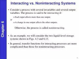
Outside the CPU • Computers must be able to communicate with the outside world • Large variety of devices • size • speed • distance • Timing and electrical properties not the same as within CPU
Single bus structure Processor Memory Bus I/O device #1 I/O device #n ............
Multiple buses Memory memory bus Processor I/O Bus I/O device #1 I/O device #n ............
Buses and interfaces Bus contains generally three bitstrings: • Data lines to transport data • Address lines to identify devices • Control lines that take care of correct transfer of data
Interfaces Devices are coupled to bus through interface: • Address decoder • for detection if data is for device • Data registers • to store incoming and outgoing data • Status and control registers • to certify status of device • to control transfer
Interface organization Address lines Data lines Control lines Address Decoder Data and Status registers I/O interface Control circuits Device
Video terminal CPU DATAIN DATAOUT SIN SOUT Keyboard Display Video terminal
Operation(1) READWAIT Branch to READWAIT if SIN=0 Input from DATAIN to R1 WRITEWAIT Branch to WRITEWAIT if SOUT=0 Output from R1 to DATAOUT Move DATAIN, R1 Move R1, DATAOUT
Operation(2) 2 1 0 IOSTATUS SIN SOUT DATAIN DATAOUT READWAIT Testbit #1, IOSTATUS Branch=0 READWAIT Move DATAIN, R1
I/O Instructions • Memory-mapped I/O • The registers of the devices have addresses in the same space as main memory locations • Normal instructions can be used • Move DATAIN, R1 • I/O instructions • special instructions for I/O • IN device, data • OUT data, device
IOPROC1 IOPROC2 Memory and register structure Mem CPU ......
Address spaces 0 0 CPU CPU 1 1 2 2 0 0 IOPROC1 1 IOPROC1 1 2 2 0 3 IOPROC1 1 IOPROC1 4 2 5 0 6 Mem Mem ...... ...... memory mapped separate address spaces
I/O and Programming There are two basic mechanisms for I/O • Programmed I/O • Non-programmed I/O
Programmed I/O • By executing of special program in CPU • Unconditional I/O • No synchronization with I/O device • Passive signaling • synchronization between CPU and Device by programmed interrogation by CPU • Active signaling • synchronization between CPU and Device by active interrupt of Device
Non-programmed I/O I/O is done by separate active entity • Direct Memory Access (DMA) • some intelligence in device takes care of data transport • Special I/O processors
Interrupts Compute routine Print routine 1 ... Interrupt i i +1 ..... ..... .... M
Service Routines • I/O device alerts CPU by hardware signal called interrupt signal • Usually special line in control group of IO bus is used for this: interrupt request line • CPU aborts program and starts executing service routine • Much like executing subroutine • Exception: routines have nothing in common ! !
Handling interrupts • Device raises interrupt request • Processor interrupts program in execution • Interrupts are disabled • Device is informed of acceptance and in turn lowers interrupt • Interrupt is handled by service routine • Execution of interrupted is resumed
Multiple devices • How can processor distinguish devices ? • How can processor obtain appropriate starting address service routine ? • Should we allow new interrupt while another is being served ? • How do we handle simultaneous interrupts ?
Interrupt line INTR = INT1 + INT2 + .... + INTn interrupt request CPU INT1 INT2 INTn Finding device by POLLING : - search for device with IRQ bit set in status register
Vectored Interrupt • Device sends identification code on bus • Called interrupts vector • Issued after GRANT signal from CPU interrupt request CPU INT1 INT2 INTn grant
Interrupt priority priority circuit CPU INT1 INT2 INTn grant1 grant2 grant3
Bus arbitration(1) bus release line (rel_i) interrupt request line (req_i) CPU grant bus is free iff (rel_1 • rel_2 • ..... • rel_n) =1
Bus arbitration(2) • Request: set req_i <- 1 • Acquire: if grant=1, then set rel_i <- 0 and req_i <- 0 • Release: set rel_i <- 1 grant = (req_1 + req_2 + ..... +req_n) •(rel_1 • rel_2 • ..... • rel_n)
Question Why does the previous scheme not always work ?
PowerPC interrupt structure MSR = Machine State Register 0 16 17 21 25 31 EE PR SE EP EE = External interrupt enable PR = Privilege level SE = Single step trace exception enable EP = Exception prefix EP=0 -> address service starts at 000001F4 EP=1 -> address service starts at FFF001F4
PowerPC • PowerPC has two special Save/Store registers: SRR0 and SRR1 • After interrupt: MSR PC SRR0 SRR1 Clear Interrupt enable bit in MSR
Example DATAIN 6 2 1 0 STATUS IE SIN SOUT interrupt keyboard interface
Memory Layout STATUS DATAIN 32 K I/O space LINE ..... ..... buffer area ..... 32 K program space 1F4 address READ READ .....
Initialization (1) INTVEC EQU $1F4 Interrupt vector address (location where start address of interrupt routine is stored) INTEN EQU $40 Keyboard interrupt enable INTDIS EQU 0 and disable masks (will be stored in status register of device) NEWMSR EQU $8000 Desired contents of MSR (external interrupt enable) RTRN EQU $0D Code Carriage Return (for checking end-of-line)
Initialization (2) START ADDI R2,0,READ Get address of service STW R2,INTVEC(0) routine and store at interrupt vector location ADDI R2,0,LINE Get address of LINE STW R2, PNTR(0) and store at PNTR ADDI R2,0,INTEN Store interrupt enable STW R2,STATUS(0) in STATUS register
Initialization (3) ADDI R2,0,NEWMSR Store new MSR MTSRR1 R2 in SRR1 ADDI R2,0,MAIN Store new PC MTSRR0 R2 in SRR0 RFI Return From Interrupt (use new MSR and PC)
Program (1) MAIN <main program> ..... READ ..... Save registers LBZ R30,DATAIN(0) Get input character LWZ R31,PNTR(0) Load value at PNTR STBU R30,1(R31) Store character in buffer STW R31,PNTR(0) Update PNTR for next character
Program (2) CMPWI CR1,R30,RTRN Check for CR (end of BNE CR1,DONE line) ADDI R2,0,INTDIS Store interrupt disable STW R2,STATUS(0) mask and clear STW R2,STATUS(0) in STATUS register BL TEXT Call subroutine for dealing with line DONE .... Restore saved registers RFI Return from interrupt
Other interrupts • Not only I/O devices can cause interrupts • Recovery from errors • Illegal OP code use • Division by 0 • Debugging • Privilege exception
Operating Systems(1) • In general interrupts controlled by Operating System • CPU in user mode or supervisor mode • Privileged instructions only allowed in supervisor mode • Starting of I/O operations • Setting of priorities • Setting of clock values
Operating Systems(2) • Process: program in execution • Program • Data • Status: PC, Registers, etc • State of process: running, runnable, blocked • Multi-tasking • Time-slicing
Operating Systems(3) • Context switch: change of processes • After clock interrupt: dispatcher chooses suitable process • Device drivers: service routines for devices • System Call: call to OS service routine • printf (“%d\n”,a) • fscanf (file,”%d\n”,&a)
OS init, services, scheduler OSINIT Set interrupt vectors Time slice clock <- SCHEDULER Trap <- OSSERVICES VDT interrupts <- IODATA ... OSSERVICES Examine stack to determine request Call appropriate routine SCHEDULER Save current context Select runnable process Restore saved context of new process Return from interrupt
I/O routines IOINIT Set process status to Blocked Initialize memory buffers Call device driver to initialize device Return from subroutine IODATA Poll devices to determine source of interrupt Call appropriate driver if END=1 then set process to Runnable Return from interrupt
VDT driver VDTINIT Initialize device interface (e.g. baud rate) Enable interrupts Return from subrouine VDTDATA Check device status If ready then transfer character If character = CR then set END=1 else set END =0 Return from subroutine
Direct Memory Access Start address Wordcount 31 30 2 1 0 Status &Control Done IE R/W IRQ DMA interface
Bus structures Specification of bus • Number of data lines • Address space • Multiplexing discipline • Control structure • Synchronous versus asynchronous • Physical properties: connectors, pinning, electrical properties
Synchronous Bus Bus clock Address Data
Asynchronous Bus(1) Address Ready Accept Data Input Cycle
Asynchronous Bus(2) Address Ready Accept Data Output Cycle
SCSI bus • Small Computer System Interface (SCSI) • ANSI X3.131 • Up to 25 meter • 50-wire cable • Up to 8 devices to bus • Initiator and target connection • Target controls data transfer
SCSI bus signals • Data DB(0),..., DB(7), DB(P) • Phase: BSY, SEL • Information: C/D, MSG • Handshake: REQ, ACK • Direction: I/O • Other: ATN, RST
Typical sequence -DB2 initiator 2 retreats target -DB5 initiator -DB6 -BSY -SEL free arbitration select