PLASMA OPERATIONS II
PLASMA OPERATIONS II. PLASMA FORMATION CURRENT RISE (FLUX CONSUMPTION) STANDARD CONFIGURATIONS TIME EVOLVED SCENARIOS MAXFEA/PROTEUS PULSE SCHEDULE EDITOR NEW CONFIGURATION FOR 2005/6 DISRUPTIONS. 44 slides. 1. BREAKDOWN AND PLASMA FORMATION. AVALANCHE PHASE

PLASMA OPERATIONS II
E N D
Presentation Transcript
PLASMA OPERATIONS II • PLASMA FORMATION • CURRENT RISE • (FLUX CONSUMPTION) • STANDARD CONFIGURATIONS • TIME EVOLVED SCENARIOS • MAXFEA/PROTEUS • PULSE SCHEDULE EDITOR • NEW CONFIGURATION FOR 2005/6 • DISRUPTIONS 44 slides P Lomas Plasma Ops II
1. BREAKDOWN AND PLASMA FORMATION AVALANCHE PHASE Breakdown in a torus Townsend discharge between electrodes inter electrode distance connection length along field lines to parts of vessel P pressure torr (750 Torr = 1000mBar). The ionisation length in meters E electric field Volts/m Vloop = 17V, E~0.91 V/mi has a minimum 78m at P ~ 6 x10⁻⁵ Torr 8 x 10⁻⁵ bar Need to go 4 times round the torus to create an ionisation! P Lomas Plasma Ops II
size of the field minimum toroidal field The connection length <Bz> is the average stray field over the null Number of ionisations per transit=LC/i Avalanche successful if LC/i >>1 P Lomas Plasma Ops II
HEXAPOLAR NULL At 20kA premag, 2turns P3m and static P4 bias 425Amp (including vessel eddy currents). Vloop = Ipre• R=20kA*0.6/710 =17volts <Bz> ~5 x 10⁻⁴over anull 0.8m Connection length Lc ~ 1100m at 2.8T. many (~14) ionisations per lifetime avalanche should occur. Need to catch Ip with net Bv and allow this to penetrate the vessel, so is better to ramp P4 from ~230amp to ~750A over the first 25ms. The null actually lasts longer because field due to inboard and outboard eddy currents cancel. Need also to compensate current in MKII divertor baseplate with radial field. P Lomas Plasma Ops II = 0.0073 Wb
Townsend expression with LC=imin electric field for avalanche Lines for various electric fields in JET Curves for different connection lengths A vertical field error of 0.5mT 38Amp in P4 halve connection length still margin! P Lomas Plasma Ops II
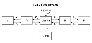
COULOMB PHASE Ionisation energy will keep the plasma cold (few eV) until all the neutrals are ionised (or driven into the wall). When fully ionised the temperature will rise to 10eV or so whereupon coulomb collisions dominate. Transition from atomic and molecular to Coulomb collisions when: /(1- ) 5 x 10⁻³ Te3/2 Where = ionization fraction: 1.4% 2 eV = 3.8% at 4 eV 10% 8 eV The current density at the transition is typically: = noeVde ~5 to 20 kA/m2 In JET, this current is 20 to 40 kA Between 10 and 20eV we reach the peak radiation from Carbon and Oxygen. Clearly must have enough power to burn through. Having burnt through the Poynting flux can then raise the plasma magnetic energy i.e. increase the plasma current. P Lomas Plasma Ops II
TYPICAL MODE D BREAKDOWN The first 100ms of JET pulse 5485. The division between avalanche and Coulomb phases is based on equation 5. BURN THRU’ P Lomas Plasma Ops II
Fortunately raising the plasma current is stabilising, so we must • Get through to 100kA quickly • Keep the plasma current increasing • Until vertical and radial control take over. CAN WE CATCH PLASMA? Whilst the plasma current is low <100kA the fields due to the plasma current are comparable to stray fields and magnetic errors. This would be OK if the initial plasma position were stable. Unfortunately it is not. The growth rate of the initial plasma in the stray fields at initiation is typically ~ 50 s-1 P Lomas Plasma Ops II
BREAKDOWN CHECKLIST OH Mode B, C or D (or even A) Premagnetisation current (P1 voltage control wave in Mode B) Prefill pressure Bias P4 (null formation) Pre-programmed P4 rise during avalanche Catch radial plasma position with flux control (in Mode C or D requires vertical field booster amps) Compensate induced currents in MKII structure and enable vertical stabilisation Activate imbalance for vertical location of plasma Activate P1 voltage reduction switches (modes C D) Sounds complicated? P Lomas Plasma Ops II
Need to change breakdown? Simply select from PlasmaOpsGroup/PremagLibrary P Lomas Plasma Ops II
P1 voltage control The proportional controller has unity gain but clips the output SC-VFGC<CS to 1.5kV which is the limit of the excitation voltage FGC-FIELD<VLT:100. The term 255/NPFGC in Lennholm`s lecture notes scales with flywheel speed. The PPCC output is converted to 10V in the digital to analogue convertor which sends the signal to the generator where it is read back as FGC_EXCTR<CHK:100. When VP1 is equal to the measured P1 voltage the generator excitation remains constant, the generator current remains constant and therefore the P1 voltage remains constant Standard Mode B uses VP1=–5kV to give maximum generator excitation then ramps to +5kV around 40.4s to give maximum de-excitation ( note waveform sign convention after reconnection, generator currents and voltages are reversed and are negative to produce an increase in plasma current. The PPCC signals themselves adopt the standard R--Z convention.). Thus VP1 saturates the excitation voltage and it is not until VP1 goes to zero at 40.6s do we have any plasma current feedback. New Mode B scheme uses VP1 as a true feed-forward for the P1 voltage. The generator is connected to the P1 coil and R3/R4 in parallel. Thus, when the P1 current is low the P1 voltage is given by the generator current times the resistance of R3/R4. To get maximum generator excitation and the maximum ramp of P1 voltage VP1 should be 1.5kV more than the measured voltage and to get maximum de-excitation VP1 should be 1.5kV less than the measured voltage (when the same sign convention is used!). When the difference between VP1 and the measured voltage is less than the saturation level of 1.5kV then plasma current feedback can be active. In PPCC the plasma current feedback contribution to SC-VP1<CS is Ip-Ipref*0.0145. Using this scheme the vigour of the initial Ip rise can be varied between 4 and 8MA/s. P Lomas Plasma Ops II
“Old” B Coloursnew B Ip Slow rise P1 volts, vary max. overshoot Vp1 mhd Wrong gas timing H Limit bounce Gen Exc Sticks at zero Can vary initial li li #52366, 60, 56, 59, 73 P Lomas Plasma Ops II
Mode B new v old Suppress premature avalanche P Lomas Plasma Ops II
CURRENT RISE INSTABILITIES • During the current rise phase, j(r) may be rather flat with steep edge gradients and this can generate instabilities as integer values of q pass through plasma edge. • At q (a)>6, these mhd modes are observed as bursts of rotating n=1 mhd activity which decay. • For q (a)<6, the modes may lock and ultimately cause a disruption. • The disruption can be delayed for many seconds and may not occur until the current decay begins. • Although the mode is initiated with m= q (a), it is found that the mode which causes the disruption has m=2, n=1, indicating that the dominant poloidal mode number changes after locking. P Lomas Plasma Ops II
MHD ACTIVITY IN THE CURRENT RISE Bursts of n=1 activity are observed at q(a)~5,4,3 and the mode locks at q(a)~3 P Lomas Plasma Ops II
The behaviour of surface kinks with m~q,n=1, during the current rise phase can be understood in terms of the li-q diagram Near the upper boundary of the diagram, disruptions (e.g. density limit) can occur as a result of the destabilization of modes on the q=2 surface. The li-q diagram See: JA Wesson et al, Nuclear Fusion 18 (1978) 87 C Z Cheng et al, Plasma Phys and Contr Fus 29 (1987) 351P J Lomas et al, JET-IR(87)19 (Proc 1987 APS) J A Snipes et al, Nuclear Fusion 28 (1988) 1085)) P Lomas Plasma Ops II
CONTROL OF CURRENT RISE INSTABILITIES Breakdown premagnetization: reducing premag reduces the rate of increase in current but wastes flux ‘Knobs’ to modify the evolution of the current profile: Thyristor switched resistors: TMS These reduce the loop voltage after breakdown and reduce the rate of current rise Changing prefill pressure or requested density waveform:increased fuelling favours a more peaked current profile, but has to be balanced against the possibility of hitting the density limit in the current rise. Ramping of toroidal field with current: break down at lower toroidal field and ramp, flux compression leads to more peaked current profile. Aperture expansion: promotes current penetration and allows, in particular, q(a)=4 to be crossed at low current; following this current can be increased at approximately constant q(a). Reduce current ramp rate in slow rise phase: Best ramp rates achievable with all of the above are ~1MAs-1. P Lomas Plasma Ops II
FLUX CONSUMPTION The absolute flux at the plasma surface is given by Pre is the flux at the end of premagnetisation and is positive for positive Ip and negative for negative Ip The second term on the RHS is the resistive flux and the third the internal inductive flux. The normalised flux inductance hi is defined from the Faraday internal flux according to Flux inductance hi versus normalised internal inductance li How to compute possible pulse length. ALL ON WEB Good for the soul, but all computerised nowadays! If we have a computed full equilibrium (Proteus or IDENTD) we have the resistive consumption immediately from P Lomas Plasma Ops II
Link to:-http://w3.jet.efda.org/pages/torus-ops/pages/op-instructions/index.html P Lomas Plasma Ops II
Fully developed configs Under development 2003/4 New for 2005/6 P Lomas Plasma Ops II
HC_SFE_LT:1 Low Triangularity d0.24 SOL surfaces 10 mid-plane mm kA/MA 6 5 -0.1 -2 5 7.2 -2 PFX SH IMB D1 D2D3D4 Standard Flux Expansion Horizontal Corner P Lomas Plasma Ops II
CONFIG. V/SFE/LT 2.5MA/2.4T V/SFE/VHT P Lomas Plasma Ops II
INTER-MACHINE SIMILARITY/IDENTITY PULSES Also EDA regime studies P Lomas Plasma Ops II
SCENARIO FOR ELMY H MODES Slow X point formation from inner limiter, slow ramp to final config. Note: Slow formation uses gas higher recycling levels Consumes flat top. Thorough current penetration P Lomas Plasma Ops II
Scenario for low q95, High Ip H Modes Small bore start upConst q limiter rise phase expanding aperture ramped TF early sawteeth ~45sq>3 limits Ip to ~3.6 MA.X Point must await P1 reversal (PFX)Continue ramp during X Fully penetrated current at start of flat top. (used up to 6 MA q95 ~2) P Lomas Plasma Ops II
X point formation for low density H modes RAPID FORMATION OF HIGHLY TRIANGULAR PULSE FROM OUTBOARD LIMITERAt this high Ip limiter phase q~3.2. Also error fields a problem near q ~3. MINIMUM DENSITYMINIMUM GASMINIMUM RECYCLING High T P Lomas Plasma Ops II
Scenario for Advanced Tokamak Breakdown without premagnetisationLarge bore minimise current penetrationEarly x with shape + divertorsPFX from 41.4Replace shape with PFX for modest triangularity.OPTIONS• Can retain large shaping for high triangularity • Can also hold limiter plasma through rise Continue current ramp beware MHD at q95~4. Start heating when desired q(r) has evolved. Timing q(o) (Typ 1-4) Ip ramp shear Can also fine tune q(o) with off axis current drive. P Lomas Plasma Ops II
MAXFEA, fast, interactive, user friendly b, li Circuits Currents Nudge buttons Options P Lomas Plasma Ops II
PROTEUS Finer mesh, more options, more outputs, more detail. Portable. < 1min/eq on PC. Less user friendly. P Lomas Plasma Ops II
Simplest pulse, limiter, using same control scheme throughout Start time Single Control Window All done with waveforms P Lomas Plasma Ops II
Need outer gap control before X point Transition FLUX to ROG Make X by ramping and holding waveforms P Lomas Plasma Ops II
Thinking of changing to a new configuration? Button computes waveforms Choose Standard scenario V/SFE/LT Result Up to here user written waveforms P Lomas Plasma Ops II
Can run almost the entire pulse using standard scenarios. Forward Transition Times Limiter X Formation HC/SFE/LT Septum Termination Dynamic phase using waveforms Still have to write ROG or RIG waveform! P Lomas Plasma Ops II
ITER-LIKE equilibrium on divertor MKIIGB Limited by D2 to about 2.7MA. 400Tonne disruption at 2.5MA! Without septum cannot increased because inner SOL spills over. However can lower X which reduces coil currents and allows higher Ip. 10mm SOL surfaces 475 Tonne at 2.7MA! P Lomas Plasma Ops II
Forward D1 d~0.48 Zero D1 d0.465 Zero D1 d0.44 3.5MA high triangularity without Septum P Lomas Plasma Ops II
3.5MA HT3up=0.44,low=0.37 D3D1 up=0.53,low=0.48 4MA HDLXup=0.43,low=0.45 3.5MA ITER up=0.45,low=0.54 Low X point P Lomas Plasma Ops II
Disruptions, large forcessignificant displacements See also Engineering Limits Lecture by I.Nunes P Lomas Plasma Ops II
Levels and windows Matrix of inputs and responses Shape Control Fast Stop initiates Fast ramp-down Set up using Plasma Protection System P Lomas Plasma Ops II
SUMMARY • Shown how to • Form plasma and ramp the plasma current avoiding instabilities • Choose configuration and optimise the scenario • An introduction equilibrium codes and the Pulse Schedule • Some equilibria for the new divertor • Mentioned some aspects of disruptions. • Tomorrow you will learn about • plasma control and new in-vessel hardware • Then get your first hands on experience with the tools. P Lomas Plasma Ops II