Download
1 / 33
390 likes | 654 Vues
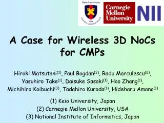
Low-Latency Wireless 3D NoCs via Randomized Shortcut Chips. Outline: Random chip for 3D WiNoCs. 3D Wireless NoCs (3D WiNoCs ) [ 7 min] Wireless 3D IC technology 3D WiNoC design example (65nm) Adding random NoC chip for 3D WiNoCs [8min]

E N D
Outline: Random chip for 3D WiNoCs • 3D Wireless NoCs (3D WiNoCs) [7min] • Wireless 3D IC technology • 3D WiNoC design example (65nm) • Adding random NoC chip for 3D WiNoCs[8min] Adding randomness induces small-world effects • Adding random NoC chip to NoC-less 3D ICs • Replacing regular 2D NoC with random 2D NoC • Design space exploration [5min] • Experiment results and Summary [5min]
Design cost of LSI is increasing • System-on-Chip (SoC) • Required components are integrated on a single chip • Different LSI must be developed for each application • System-in-Package (SiP) or 3D IC • Required components are stacked for each application By changing the chips in a package, we can provide a wider range of chip family with modest design cost
3D IC technology for going vertical Wired Wireless Flexibility Two chips (face-to-face) Microbump Capacitive coupling Scalability More than three chips Through silicon via Inductive coupling
3D Wireless NoC (3D WiNoC) Three chips are stacked wirelessly Each router has a wireless transceiver Each router has TX/RX coils (inductors) Coils are implemented with metal layers Chip#2 TX Chip#1 Chip#0 RX
An example: Cube-1 (2012) • Test chips for building-block 3D systems • Two chip types: Host CPU chip & Accelerator chip • We can customize number & types of chips in SiP • Cube-1 Host CPU chip • Two 3D wireless routers • MIPS-like CPU • Cube-1 Accelerator chip • Two 3D wireless routers • Processing element array [Miura, IEEE Micro 13] MIP CPU Core Inductors 8x8 PE Array
An example: Cube-1 (2012) We can change the number and types of chips in a package according to application requirements • Microphotographs of test chips [Miura, IEEE Micro 13] Host CPU Chip Host CPU + 3 Accelerators Accelerator Chip
An example: Cube-0 (2010) Either vertical P2P links or broadcast bus can be formed for 3D WiNoC • Test chip for vertical communication schemes • Vertical point-to-point link between adjacent chips • Vertical shared bus (broadcast) 2.1mmx 2.1mm [Matsutani, NOCS’11] TX RX Inductors (P2P) Core 0 & 1 Stacking for Ring network TX/RX Router 0 & 1 Stacking for Vertical bus Inductors (bus)
Outline: Random chip for 3D WiNoCs • 3D Wireless NoCs (3D WiNoCs) [7min] • Wireless 3D IC technology • 3D WiNoC design example (65nm) • Adding random NoC chip for 3D WiNoCs[8min] Adding randomness induces small-world effects • Adding random NoC chip to NoC-less 3D ICs • Replacing regular 2D NoC with random 2D NoC • Design space exploration [5min] • Experiment results and Summary [5min]
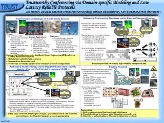
Big picture: 3D Wireless NoC • Arbitrary chips are stacked after fabrication • Each chip has vertical links at pre-specified locations, but we do not know internal topology of each chip • Some chips may not have horizontal NoC (vertical link only) CPU chip from A Required chips are stacked for each application Application chip from B Memory chip from C An example (4 chips) Inductor (vertical link)
Big picture: 3D Wireless NoC • Arbitrary chips are stacked after fabrication • Each chip has vertical links at pre-specified locations, but we do not know internal topology of each chip • Some chips may not have horizontal NoC (vertical link only) Adding randomness induces small-world effect Here we examine two cases: Adding random NoC chip to NoC-less 3D ICs Replacing regular 2D NoC with random 2D NoC CPU chip from A Required chips are stacked for each application Application chip from B Memory chip from C An example (4 chips) Inductor (vertical link)
Big picture: 3D WiNoC w/ Random • Router IP macros have the same # of ports • Unused ports can be used for long-range links • In addition, redundant links are implemented and statically multiplexed by FPGA-like switch boxes • By reconfiguring the switch boxes, an unique random wire pattern can be generated
Big picture: 3D WiNoC w/ Random • Router IP macros have the same # of ports • Unused ports can be used for long-range links • In addition, redundant links are implemented and statically multiplexed by FPGA-like switch boxes • By reconfiguring the switch boxes, an unique random wire pattern can be generated
Case 1: Random NoC to NoC-less 3D ICs • Each chip has inductors but does not have 2D NoC • Inductors in the same pillar form a vertical broadcast bus • Horizontal connectivity is not provided at all (i.e., NoC-less) Chip#2 Chip#2 NoC-less Vertical broadcast bus Chip#1 NoC-less Chip#1 Chip#0 NoC-less Chip#0 Side view (3 chips) “― ― ―” Configuration
Case 1: Random NoC to NoC-less 3D ICs • Each chip has inductors but does not have 2D NoC • Inductors in the same pillar form a vertical broadcast bus • Adding a 2D Mesh NoC to such NoC-less 3D IC Chip#2 Chip#2 2D Mesh Destination Chip#1 NoC-less Chip#1 Source Chip#0 NoC-less Chip#0 Side view (3 chips) “m ― ―” Configuration
Case 1: Random NoC to NoC-less 3D ICs • Each chip has inductors but does not have 2D NoC • Inductors in the same pillar form a vertical broadcast bus • Adding a Random NoC to such NoC-less 3D IC Chip#2 Chip#2 Random Destination Chip#1 NoC-less Chip#1 Source Chip#0 NoC-less Chip#0 Side view (3 chips) “r ― ―” Configuration
Case 1: Random NoC to NoC-less 3D ICs • Each chip has inductors and partially has 2D NoC • Inductors in the same pillar form a vertical broadcast bus • We call this configuration partial-NoC 3D IC Chip#2 Chip#2 NoC-less Destination Chip#1 NoC-less Chip#1 Source Chip#0 2D Mesh Chip#0 Side view (3 chips) “― ― m” Configuration
Case 1: Random NoC to NoC-less 3D ICs • Each chip has inductors and partially has 2D NoC • Inductors in the same pillar form a vertical broadcast bus • Adding a Random NoCto a partial-NoC 3D IC Chip#2 Chip#2 Random Destination Chip#1 NoC-less Chip#1 Source Chip#0 2D Mesh Chip#0 Side view (3 chips) “r ― m” Configuration
Case 2: Replacing regular NoC w/ random • 3D WiNoC that consists of three 2D Mesh NoC layers • Inductors in neighboring chips form a vertical P2P link • E.g., regular 3D Mesh topology (i.e., regular 3D NoC) Chip#2 Chip#2 2D Mesh Vertical point-to-point link Chip#1 2D Mesh Chip#1 Chip#0 2D Mesh Chip#0 Side view (3 chips) “mm m” Configuration
Case 2: Replacing regular NoC w/ random • 3D WiNoC that consists of three 2D Mesh NoC layers • Inductors in neighboring chips form a vertical P2P link • Replacing regular 2D Mesh with random NoC Chip#2 2D Mesh Chip#2 2D Mesh Chip#1 2D Mesh Chip#1 Random Chip#0 2D Mesh Chip#0 2D Mesh “mm m” Configuration “mr m” Configuration
Routing: Spanning tree optimization • Packets are routed based on up*/down* rule • Up & Down directions are assigned based on root node • Packets go up and then go down Spanning tree root is selected based on an optimization method [Matsutani,ASPDAC’13] OK Root Chip 3 Chip 3 0 0 1 1 You can use either VC0 or VC1 Chip 2 Chip 2 OK 2 2 3 3 Chip 1 Chip 1 4 4 5 5 Chip 0 Chip 0 VC1 VC0 6 6 7 7 Root’
Outline: Random chip for 3D WiNoCs • 3D Wireless NoCs (3D WiNoCs) [7min] • Wireless 3D IC technology • 3D WiNoC design example (65nm) • Adding random NoC chip for 3D WiNoCs[8min] Adding randomness induces small-world effects • Adding random NoC chip to NoC-less 3D ICs • Replacing regular 2D NoC with random 2D NoC • Design space exploration [5min] • Experiment results and Summary [5min]
Q1: How many random chips do we need? Number of random chips vs. Average latency P2P Bus P2P Bus 1 random chip drastically reduces latency # of random chips (16-node) # of random chips (64-node)
Q1: How many random chips do we need? Number of random chips vs. Average latency P2P Bus P2P Bus 1 or 2 random chips are enough in the P2P case # of random chips (16-node) # of random chips (64-node)
Q2: How should we design random chip? Max. link length (left) & Horizontal degree (right) P2P Bus P2P Bus Double-length link is enough (equivalent to folded torus) 4 ports are enough (equivalent to 2D mesh/torus) Max random link length [tile] # of Horizontal router ports
Outline: Random chip for 3D WiNoCs • 3D Wireless NoCs (3D WiNoCs) [7min] • Wireless 3D IC technology • 3D WiNoC design example (65nm) • Adding random NoC chip for 3D WiNoCs[8min] Adding randomness induces small-world effects • Adding random NoC chip to NoC-less 3D ICs • Replacing regular 2D NoC with random 2D NoC • Design space exploration [5min] • Experiment results and Summary [5min]
Full-system simulations (gem5) L2 cache banks Table 1: Topologies to be examined CPU CPU Table 2: Simulation parameters m - r Table 3: Application programs
Packet latency: P2P (mmmmmrrmrrrr) m mmm m rr m rrrr Average packet latency [cycles] rrrr reduces latency by 20.7% compared to mmmm
Packet latency: Bus (---m ---r m--r) --- m - - - r m - - r Average packet latency [cycles] ---r reduces latency by 26.2% compared to ---m
App. exec time: P2P (mmmmmrrmrrrr) m mmm m rr m rrrr App execution time (normalized) rrrr improves exec time by 6.6% compared to mmmm
App. exec time: Bus (---m ---r m--r) --- m - - - r m - - r App execution time (normalized) ---r improves exec time by 7.1% compared to ---m
Summary: Random NoC to 3D WiNoCs • 3D Wireless NoC (3D WiNoC) • We can add necessary chips to build custom SiP • Example: Cube-1 (1 CPU chip + 3 Accelerator chips) Adding randomness induces small-world effect • Two case studies • Adding random NoC chip to NoC-less 3D ICs • Replacing regular 2D NoC with random 2D NoC • Reasonable solution • Adding one or two random chips is enough • Horizontal degree = 4; Max random link length = 2 • Experimental results • Packet latency is improved by 26.2% • Application execution time is reduced accordingly
Thank you for listening! Cube-1 demo system PE array chip performs image processing; CPU chip for control Cube-1 [Miura, HotChips’13 Demo] Motherboard 33