Networks-on-Chips ( NoCs) Basics
440 likes | 1.01k Vues
Networks-on-Chips ( NoCs) Basics. ECE 284 On-Chip Interconnection Networks Spring 2013. Examples of Tiled Multiprocessors. 2D -mesh networks often used as on-chip fabric. 12.64mm. I/O Area. single tile. 1.5mm. 2.0mm. 21.72mm. Tilera Tile64. I/O Area. Intel 80-core.

Networks-on-Chips ( NoCs) Basics
E N D
Presentation Transcript
Networks-on-Chips (NoCs)Basics ECE 284 On-Chip Interconnection Networks Spring 2013
Examples of Tiled Multiprocessors • 2D-mesh networks often used as on-chip fabric 12.64mm I/O Area single tile 1.5mm 2.0mm 21.72mm Tilera Tile64 I/O Area Intel 80-core
Typical architecture Compute Unit • Each tile typically comprises the CPU, a local L1 cache, a “slice” of a distributed L2 cache, and a router Router L1 Cache CPU Slice of L2 Cache
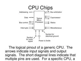
Router function • The job of the router is forward packets from a source tile to a destination tile (e.g., when a “cache line” is read from a “remote” L2 slice). • Two example switching modes: • Store-and-forward: Bits of a packet are forwarded only after entire packet is first stored. • Cut-through: Bits of a packet are forwarded once the header portion is received.
Buffers for data packets Store-and-forward switching Store Source end node Destination end node Packets are completely stored before any portion is forwarded [adapted from instructional slides of Pinkston & Duato, Computer Architecture: A Quantitative Approach]
Requirement: buffers must be sized to hold entire packet Store-and-forward switching Forward Store Source end node Destination end node Packets are completely stored before any portion is forwarded [adapted from instructional slides of Pinkston & Duato, Computer Architecture: A Quantitative Approach]
Buffers for data packets Requirement: buffers must be sized to hold entire packet Buffers for flits: packets can be larger than buffers Cut-through switching • Virtual cut-through Source end node Destination end node • Wormhole Source end node Destination end node [adapted from instructional slides of Pinkston & Duato, Computer Architecture: A Quantitative Approach]
Buffers for data packets Requirement: buffers must be sized to hold entire packet (MTU) Buffers for flits: packets can be larger than buffers Cut-through switching • Virtual cut-through Busy Link Packet completely stored at the switch Source end node Destination end node • Wormhole Busy Link Packet stored along the path Source end node Destination end node [adapted from instructional slides of Pinkston & Duato, Computer Architecture: A Quantitative Approach]
Packets to flits [adapted from Becker STM’09 talk]
Wormhole routing • Head flit establishes the connection from input port to output port. It contains the destination address. • Body flits goes through the established connection (does not need destination address information) • Tail flit releases the connection. • All other flits blocked until connection is released
Virtual channels • Share channel capacity between multiple data streams • Interleave flits from different packets • Provide dedicated buffer space for each virtual channel • Decouple channels from buffers • “The Swiss Army Knife for Interconnection Networks” • Prevent deadlocks • Reduce head-of-line blocking • Also useful for providing QoS [adapted from Becker STM’09 talk]
Using VCs for deadlock prevention • Protocol deadlock • Circular dependencies between messages at network edge • Solution: • Partition range of VCs into different message classes • Routing deadlock • Circular dependencies between resources within network • Solution: • Partition range of VCs into different resource classes • Restrict transitions between resource classes to impose partial order on resource acquisition • {packet classes} = {message classes} × {resource classes} [adapted from Becker STM’09 talk]
Using VCs for flow control • Coupling between channels and buffers causes head-of-line blocking • Adds false dependencies between packets • Limits channel utilization • Increases latency • Even with VCs for deadlock prevention, still applies to packets in same class • Solution: • Assign multiple VCs to each packet class [adapted from Becker STM’09 talk]
VC router pipeline • Route Computation (RC) • Determine candidate output port(s) and VC(s) • Can be precomputed at upstream router (lookahead routing) • Virtual Channel Allocation (VA) • Assign available output VCs to waiting packets at input VCs • Switch Allocation (SA) • Assign switch time slots to buffered flits • Switch Traversal (ST) • Send flits through crossbar switch to appropriate output Per packet Per flit [adapted from Becker STM’09 talk]
Allocation basics • Arbitration: • Multiple requestors • Single resource • Request + grant vectors • Allocation: • Multiple requestors • Multiple equivalent resources • Request + grant matrices • Matching: • Each grant must satisfy a request • Each requester gets at most one grant • Each resource is granted at most once [adapted from Becker STM’09 talk]
Separable allocators Input-first: • Matchings have at most one grant per row and per column • Implement via to two phases of arbitration • Column-wise and row-wise • Perform in either order • Arbiters in each stage are fully independent • Fast and cheap • But bad choices in first phase can prevent second stage from generating a good matching! Output-first: [adapted from Becker STM’09 talk]
Wavefront allocators • Avoid separate phases • … and bad decisions in first • Generate better matchings • But delay scales linearly • Also difficult to pipeline • Principle of operation: • Pick initial diagonal • Grant all requests on diagonal • Never conflict! • For each grant, delete requests in same row, column • Repeat for next diagonal [adapted from Becker STM’09 talk]
Wavefrontallocator timing • Originally conceived as full-custom design • Tiled design • True delay scales linearly • Signal wraparound creates combinational loops • Effectively broken at priority diagonal • But static timing analysis cannot infer that • Synthesized designs must be modified to avoid loops! [adapted from Becker STM’09 talk]
Diagonal Propagation Allocator • Unrolled matrix avoids combinational loops • Sliding priority window activates sub-matrix cells • But static timing analysis again sees false paths! • Actual delay is ~n • Reported delay is ~(2n-1) • Hurts synthesized designs [adapted from Becker STM’09 talk]
VC allocation • Before packets can proceed through router, need to acquire ownership of VC at downstream router • VC allocator matches unassigned input VCs with output VCs that are not currently in use • P×V requestors (input VCs), P×V resources (output VCs) • VC is acquired by head flit, inherited by body & tail flits [adapted from Becker STM’09 talk]
VC allocator implementations • Not shown: • Masking logic for busy VCs [adapted from Becker STM’09 talk]
Typical pipelined router RC VA ST LT SA route computation VC + switch allocation switch traversal link traversal