Download
1 / 24
250 likes | 426 Vues
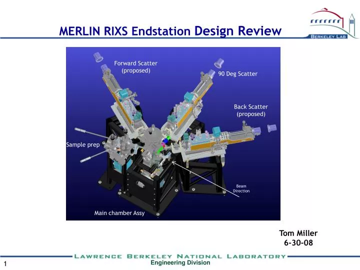
MERLIN RIXS Endstation Design Review. Forward Scatter (proposed). 90 Deg Scatter. Back Scatter (proposed). Sample prep. Beam Direction. Main chamber Assy. Tom Miller 6-30-08. Basic layout of MERLIN RIXS Endstation. ARPES Endstation. RIXS KB Mirrors. 4.0.1 Experiments.

E N D
MERLIN RIXS Endstation Design Review Forward Scatter (proposed) 90 Deg Scatter Back Scatter (proposed) Sample prep Beam Direction Main chamber Assy Tom Miller 6-30-08
Basic layout of MERLIN RIXS Endstation ARPES Endstation RIXS KB Mirrors 4.0.1 Experiments
RIXS Endstation Chamber includes 3 ports for spectrometers at 45, 90 and 150 degrees. The sample transfer port is at 195 degrees. A John Pepper designed cryostat sits on top of a 150mm travel XYZ stage mounted on an 8” rotary axis. The rotary axis is limited to 270 degrees of total travel.
RIXS Support and Pumping Details Stand is designed for maximum rigidity with allowable footprint. The shear plate is not shown. The pumping tree will initially have a 150 l/s pump installed, but the support is designed for a double-flanged 300 l/s model.
Sample Prep Sample prep with a loadlock chamber. View ports give views of transfers between chambers. Basic sample garage design
Spectrograph and Slit Assembly Overview Camera shown at minimum and maximum working distance
Spectrograph Fundamentals The slitless emission spectrograph will be used at the MERLIN branch line to perform the resonant inelastic X-ray scattering spectroscopy (RIXS) at the transition metal M edge (30-150eV). The schematic plot of the spectrograph is shown in figure 1. Figure 1: Schematic plot of the slitless VLS spectrograph that will be used at MERLIN beamline. This spectrograph has two optical components: a spherical focusing mirror and two VLS plane gratings (central line density 2000 and 3000 l/mm). The optical design is shown in figure 2. 977-1282mm This Page courtesy of Yi-De Chuang 5-20-08 Figure 2: Optical layout of the spectrograph.
Alignment, resolution and stability requirements for the spectrograph See figure 1 for coordinate system *Survey tolerance **This is a consequence of the Z-axis resolution This Page courtesy of Yi-De Chuang 5-20-08
Spectrometer Stand Kinematic base plate allows spectrometer to be removed and replaced with high accuracy. Spectrometer mounts with one shoulder bolt and compression spring for safety and repeatability Slide on Y-strut allows high-precision translation of grating or slit
Y axis translation Mechanism Travel stops on slide prevent damage to slit assembly.
Spectrometer translation mechanism Custom low-profile high rigidity crossed-roller slide. Slide shown fully extended Slide shown fully retracted. Note only one pinch point - at full extension.
Spectrometer Optics Chamber mounting Drilled and tapped mounting bars will be welded to .38” thick tank bottom. Tank was originally held by clamps on input and output tubes. Note bosses for 3-point mounting.
Spectrometer and slit assembly The white spectrometer base plate allows complete off-line alignment of the mirror tank, slits and camera assembly.
Slit Fundamentals If slits are used, the requirements are as follows: • Minimum gap < 5 microns, maximum 400 microns • Mechanism must fit inside the radiation shielding of the cryostat • Be insertible to within 5mm of the sample • Be retractable to allow the Main chamber to be valved out prior to removal of the spectrograph. Total motion required is 9.75”. • Fit inside a 1.87 ID port with clearance to move +/-0.1” in Y • Have step resolution for gap of <=1 micron using manual micrometer heads
Slit Assembly The 2 unused ports in the cross will be used for roughing out the slit and potentially for LVDT connector(s). Isolation bellows Translationbellows
Slit Details Stop plate on actuation end of slit assembly has 4-40 stop holes top and bottom to prevent over closing. Plate itself functions as a stop in the open direction. Slit will open >500 microns if the levers are driven to the stops, but no damage will result. Round holes in stop plate are for LVDT wires. Levers are inserted into the assembly from the actuation end with the stop plate removed.
Slit Lever Details Levers are made from 6061-T6 and are identical top and bottom. Note ball seat and extension spring hole on actuation end. Also note ledge at blade end to prevent blade damage by over-closing. Slit is fully closed in the relaxed state. The stress on the 17-4 strip flexures when open to 500 microns is about 75 ksi. Levers will include provisions for LVDT’s, but none will be installed initially. The LVDT mounting location will yield true slit opening if one LVDT is used or relative blade locations (yielding gap and position of gap) if 2 are used.
Slit Feedthrough Detail Tension spring keeps the lever loaded against the micrometer and the compression spring nearly cancels the vacuum loading from the bellows. This allows the micrometer to see a 3 lb thrust when under vacuum. At air, the required thrust is 6 lb. Gold cylinder is a linear bearing. Orange disk is a shim that allows large adjustments of the micrometer zero. Small changes are made by moving the micrometer in the clamp. Green-gray spring mount slips into cross.
Slit Mechanism Mounting The slit mechanism is independently alignable to the spectrometer. The opposing bellows make this alignment independent of vacuum forces. The 4 tooling balls on the mirror tank will be fiducialized to the grating. The position of the slit can then be related to the tooling balls.
Spectrograph Camera Camera is mounted to a standard 12” travel slide. Slide includes a linear encoder, index mark and limit switches. White shim plates allow alignment of the camera spool to the exit flange of the mirror tank.
Camera Bellows Support Low cost linear bushings ride on stainless guide rods.
Slit to Cryostat Relationship Note the intrusion of the slit into the cryostat assembly during use. Hard stops on the manipulator Y-axis will be required.