Lecture 3: Basic Electronics & Lab Safety Prof. Wing-Kin (Ken) Ma
610 likes | 761 Vues
ENGG 1100 Introduction to Engineering Design. Lecture 3: Basic Electronics & Lab Safety Prof. Wing-Kin (Ken) Ma Department of Electronic Engineering

Lecture 3: Basic Electronics & Lab Safety Prof. Wing-Kin (Ken) Ma
E N D
Presentation Transcript
ENGG 1100 Introduction to Engineering Design Lecture 3: Basic Electronics & Lab Safety Prof. Wing-Kin (Ken) Ma Department of Electronic Engineering Acknowledgement: those who helped develop this slide over the years, particularly, Mr. Hoi-To Wai(now with UC Davis), and Dr. Matthew Tang (now with Queen Mary University of London); also Prof. Alex Leung at electronic engineering, CUHK. Some of the pictures were obtained from the internet. January 27, 2014
Objectives • To understand basic circuits concepts, namely, voltage, current and resistors. • To introduce to you how voltage and current are measured. • To talk about lab safety. Note that • these concepts are relevant to Lab 2 (today’s lab); • you may have learnt these basic concepts in secondary school physics courses, but you need to better understand them in this course (or perhaps you might have never truly understood them).
References • An optional, very friendly, reference: Forest M. Mims III, Getting Started in Electronics
Some Electronic Components • Resistors – providing resistance (actually every matter on earth is a resistor) • Capacitors – storehouse for charges Source: http://en.wikipedia.org/wiki/Resistor Source: http://www.electronicrepairguide.com/smd-resistor-code.html Source: http://en.wikipedia.org/wiki/Capacitor
Electronic Component Symbols • Electronic components are represented using standardized symbols:
Circuits & Schematics • What do the real circuits & schematics look like… • A circuit is a connection of different electronic components.
Pentium 4 CPU Quad-core CPU These are also circuits, in a much more complex way
William Schockley (Inventor of transistor) Point-contact transistor invented in 1947 at Bell lab. Transistors Scaling down the size of the components and put all components in a small area IC = Transistors and integrated circuits (ICs)
press/release transistor switch or What does a transistor do? • Transistors play an indispensable role in electronics and other areas. • Simply speaking, a transistor works like an electronic switch (It can also perform signal amplification, e.g. in HiFi).
Transistors, together with other components, like resistors, capacitors, inductors, diodes, …, enable us to build many different circuits. Example: Use of transistors enables digital logics. With digital logistics, we can compute (without doing it ourselves)… And with the ability to compute, we have modern computers (and that includes your iPhone). A A Out Out AND OR B B A A B B Okay, so what’s the big deal?
So we build things bigger and bigger to compute, and yet size smaller and smaller Electronic Delay Storage Automatic Calculator in 1949 (addition, subtraction, multiplication, square, prime numbers, etc.) (You do know what these gadgets are, don’t you)
Electronics provides “primal elements” behind almost all modern technology. Roughly speaking, it gives us the key building blocks for fields like wireless communications, optical communications, information technology, biomedical engineering, and many, many more. Without electronic and associated engineering technologies, we may not have mobile, internet, FB or Whatsapps (which some of you might be using in my lecture). Oh, wash you own clothes (by hand), too! Who is he?
Resistor Circuits • Consider the following simple resistor circuit: Power supply Resistor • The famous Ohm’s Law:
A Circuit and its water analogy • Note: do not take these analogies too far. Water level – Voltage (V) Slit/opening – Resistance (R) Water – Charge (Q) Stream – Current (I) The famous Ohm’s Law:
Another (awkward) analogy I might use • Note: again it could be misleading!
Voltage, Current and Resistance • Current • describes the flow of positive charges through the circuit • measured in units of Amperes (A) • is, by theory, defined as where I is the current, and Q is the charge, in Coulombs (C).
Voltage, Current and Resistance • Voltage • describes the potential for current to flow in the circuit • measured in units of Volts (V) • Voltage is related to energy, measured in Joules. • The energy required to move a particle with Q Coulombs from a place of 0 V to a place with V V is where E represents the energy (in Joules).
Voltage, Current and Resistance • Resistor • is a device that resists the flow of current • allows current to flow, but the amount depends on the value of the resistor and the voltage applied • The value of the resistor, or simply resistance, is measured in units of Ohms(Ω) • By Ohm’s law, we have where R represents the resistance (in Ω).
Voltage, Current and Resistance • Power • is the rate of energy dissipation with respect to time • is in units of Joules per second, or Watts (W) • is given by where P represents the power (in W). • By Ohm’s law, we have
Basic circuit analysis • The Ohm’s law • Don’t be afraid of the equations
Resistors in series • We have • Equivalent resistance:
Resistors in parallel • Voltage on each resistor = the same: • Current coming in = current coming out: • Equivalent resistance
Kirchhoff’s circuit laws • Two important theorems for circuit analysis Kirchhoff’s current law (KCL) Kirchhoff’s voltage law (KVL) Net current entering a node = 0 Net voltage in a loop = 0 (CAUTION: mind the direction/sign of current and voltage)
Application -- voltage divider • We probably don’t need something as complex as the last example • Consider the resistors in series again: (let N=2) • The supplied voltage V is divided into two parts • This principle is called the Voltage Divider
Application – current divider • Consider the resistors in parallel : (let N=2) • The current I is divided into two parts • More current flows in the branch with less resistance • This principle is called the Current Divider
Units and dimensions • International System of Units (SI) takes the convenience of the base 10 (decimal) system. • A prefix may be added to a unit to produce a multiple (powers of ten) of the original unit. Example 1: 10 mA = 10 x 10-3 A = 0.01A Example 2: 0.3 MΩ = 0.3 x 10⁶Ω = 300 000 Ω
Electronic Color Code b a c a c b Resistor ) ] × ) × 10 + ( ( ) Resistance=[ ( ‘s value ‘s value ‘s multiplier Example: Resistance = BlueRedOrange = 62 × 1000 = 62000Ω
Basic rules for connecting a circuit • RULE #1 – a circuit must contain a closed loop • Without a closed loop, a circuit is said to be open • An open circuit cannot function as there is no returning path for current
Basic rules for connecting a circuit • RULE #2 – a circuit (usually) contains a power source • The power source provides power to make the circuit function Showing different ways of representing a power source
Basic rules for connecting a circuit • RULE #3 – electronic components are connected to a node • The lines in a schematic serve only one purpose – to make connections between components Three seemingly different schematics. They are actually describing the same circuit.
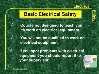
Measurement of Voltage and Current • Multimeters are all-in-one devices that measure different electrical quantities • Current (I), voltage (V), resistance (R) in one device
Application -- ammeter • Ammeters are devices that measure the Current (I) • Galvanometer (found in the analog ammeters) • The needle movement is proportional to the current I • Typical range: from 0A to 1mA Source: http://www.tpub.com/neets/book16/68.htm
Application -- ammeter • Using an ammeter to measure current at a point: • “Break” the circuit and insert the ammeter Equivalent model of an ammeter -- the internal resistance of the galvanometer -- can be adjusted for range selection (current divider)
Application -- ammeter The current reading is 0.51 mA Circuit connected in series
Application -- voltmeter • Voltmeters are devices that measure the Voltage (V): • Voltage is defined relatively must be measured “between two points” Equivalent model of a voltmeter • Very large, typical range = 200k Ω - 1M Ω • only a small current will flow through • the voltmeter (current divider) • can be adjusted to select the range
Application -- voltmeter The voltage reading is 5.03 V Circuit connected in parallel
Application -- ohmmeter • Ohmmeters are devices that measure the Resistance (R): • Resistance is also defined between two points • Just like the voltmeter • An ohmmeter = an ammeter + battery • From Ohm’s Law, Equivalent model of an ohmmeter
Question 1 • Express the voltage Va as a function of V, R1 and R2
Question 2 • What is the current measured by the ammeter?
Question 3 • What is the resistance measured by the ohmmeter?
You (probably) don’t want to do this in the lab… http://www.youtube.com/watch?v=JCPXckfT-6g