Download
1 / 17
170 likes | 315 Vues
This presentation outlines advanced strategies in the development of (Al)GaAs-GaN heterojunction bipolar transistors (HBTs). It covers wafer fusion at scalable temperatures, current aperture vertical electron transistors (CAVET), and the characterization of fused interfaces through SIMS and TEM techniques. Emphasis is placed on minimizing dopant diffusion, achieving high breakdown voltages, and optimizing device performance through advanced etching and regrowth methods. The findings suggest significant improvements in reliability and efficiency for next-gen GaN power devices.

E N D
Innovative Processing for GaN Power Devices Ilan Ben-Yaacov, Yan Gao, Sarah E. Monteith, S. DenBaars, U. Mishra, E.L. Hu University of California, Santa Barbara with thanks to Andrew Huntington, Stacia Keller, Andreas Stonas (UCSB)
Outline • Next steps for (Al)GaAs-GaN HBTs • Wafer fusion • Current Aperture Vertical Electron Transistor (CAVET) • Through MOCVD regrowth • Through selective etching
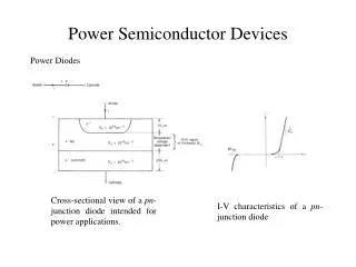
Structure AlGaAs-GaAs emitter-base high mobility carriers well-understood emitter-base interface p contacts to GaAs base (rather than to p GaN) n-GaN collector High-breakdown voltages possible Formation of (Al)GaAs-GaN HBT n-AlGaAs Emitter fused interface p-GaAs Base n-GaN Collector • In previous reviews • demonstrated reliable fusion of GaAs-GaN : 500 -750 oC, 0.5-2 hours • used SIMS, TEM, I-V measurements to characterize fused interface • Carried out initial electrical characterization of (Al)GaAs-GaN HBT
Starting Materials Fuse under 2MPa pressure at 500-750°C for 0.25-2hr GaAs GaN 1 to 4 monolayers GaAs Spray etch to remove GaAs substrate 5 nm GaN GaAs Courtesy J. Jasinski Ex situ fusion and the fused interface Fused at 750oC for 15 minutes A uniform, relatively smooth interface
Common Emitter Characteristic IB Step Size = 2mA 1.8 1.6 Au/Ge/Ni415oC 1.4 1.2 1 100 nm n-GaAs (1x10¹⁹ Si) Collector Current (mA) 0.8 30 nm Graded AlxGa1-xAs (5x10¹⁷ Si, x = 0 - 0.3) 0.6 0.4 120 nm n-AlxGa1-xAs (5x10¹⁷ Si, x = 0.3) 0.2 0 30 nm Graded AlxGa1-xAs (5x10¹⁷ Si, x = 0.3 – 0) 0 5 10 15 20 25 30 V (Volts) EC 150 nm p-GaAs Zn/Au (1x10¹⁹ C) Al/Au >2 m uid-GaN (~5x10¹⁶ Si) (001) sapphire substrate (Al)GaAs-GaN HBT Structure 20 micron x 52 micron emitter mesa GaAs/GaN Interface fused at 750oC for 1 hour
Relatively small VCE offset (~1 V): can be improved with anneal p-GaAs contacts Reasonably good output conductance (~ mA; few hundred A/cm2) Low current gain (< 1) large base width (150 nm) dopant profile after fusion? (AlGaAs-GaAs and GaAs-GaN) recombination at the fused interface? Common Emitter Characteristic IB Step Size = 2mA 1.8 1.6 1.4 1.2 1 Collector Current (mA) 0.8 0.6 0.4 0.2 0 0 5 10 15 20 25 30 V (Volts) EC (Al)GaAs-GaN HBT IV Characteristics
Base-Emitter Junction (pGaAs-nAlGaAs) p-GaAs/ n-GaAs n-AlGaAs GaN 25 E B C 20 15 6.5x10⁻³ Wcm2 Current Density (A/cm2) 10 5 0 -5 -2 -1.5 -1 -0.5 0 0.5 1 1.5 Applied Bias (Volts) (Al)GaAs-GaN HBT: Next Steps • Set fused interface slightly into collector region • n-AlGaAs/p-GaAs/n-GaAs/n-GaN • Allows for uncertainties in GaAs-GaN band lineups • Previous experience indicates that n-AlGaAs/p-GaAs/n-GaAsstructure will go through fusion process intact • Reduce base layer thickness • Carry out fusion at lower temperatures • Minimize dopant diffusion across fused interface Same characteristics before and after fusion
High-Field Region 2DEG IDS Regrown Channel GaN CAVET • Current Aperture Vertical Electron Transistor • Current flows vertically from sources to drain • Electron flow through aperture modulated by the gate • High-field region below the gate instead of at the surface (as in a HEMT) • Higher breakdown voltages • When optimized, reduction in DC-RF dispersion
1. MOCVD growth of drain and insulating regions 2. Cl2 RIE etch of aperture region 3. MOCVD maskless regrowth of aperture and source region, pattern device mesa, and deposit metal contacts CAVET Process Flow
1. Ideal device, pinch-off occurs between gate and aperture. When aperture region is too insulating, pinch- off occurs across the aperture and current does not saturate due to DIBL. 2. CAVET: Theoretical Models
For this device: • Ws = 2*Wg = 200 mm, Lap = 0.6 mm, and • Lgo = 2 mm • IDSS = 430 mA/mm, extrinsic gm = 100 mS/mm, • Vp = - 4 V • Parasitic leakage current observed at pinch-off • For all devices: • IDSS and leakage current at pinch-off • independent of Lap • IDSS and pinch-off leakage current increase • when Lgo is decreased CAVET: DC Electrical Results
1000 W Hg/Xe lamp (~20 W/cm2) GaN filter Au wire KOH:H2O Sample sapphire Etched-Aperture GaN CAVET Al0.30Ga0.70N (220Å) AlGaN AlGaN 0.5 micron uid- GaN InxGa1-xN (600Å) x = 0.07 InGaN 1.7 microns n- GaN sapphire • Create an etched aperture • Use an etch process that rapidly and selectively etches a sacrificial layer (InGaN) PhotoElectroChemical (PEC) Wet Etching Pt coil
hn After Etching 3 min, 1000 W, 2.2 M KOH I bias = 40 mA SiO2 Ni/Au GaN InGaN GaN GaN InGaN GaN sapphire Bandgap-Selective PEC Etching GaN filter will select wavelengths that only excite carriers in InGaN Approximate absorption edge of InGaN PROBLEM: roughness of undercut etch RESPONSE: Taguchi experiment to identify most critical etch parameters
MRS PEC etching 50µm 1.24V 2.71V 0.62V top view of undercut Optimization of Etch Conditions TOP-DOWN VIEWS OF ETCHED STRUCTURES KOH concentration • Systematically varied • KOH concentration • illumination power • bias applied to sample • Evaluated • lateral etch rate • smoothness of etch front • roughness of etched surface • Overwhelming dependence on KOH concentration: lower concentration produced smoother etched surface 1.24V 2.71V 0.55M 0.62V 2.71V 1.24V 0.62V 2.2M Etched area Unetched area 8.8M Illumination power 170W 400W 600W
Etched CAVET: future work • Taguchi experiments helped to identify critical etch parameter: KOH concentration • Samples etched at 0.001 M KOH, 1000W, no bias, showed smooth, well-controlled undercut • Future work: fabricate full CAVET device, using optimized etch conditions
Summary • Initial electrical characterization of first (Al)GaAs-GaN fused HBT • Try ‘setback’ of fused interface, lower fusion temperature, thinner base region • Initial CAVET device results for regrown structures • Optimize device structure and growth conditions • Optimization of PEC etching for etched CAVET devices • Fabricate and characterize full CAVET device