Download
1 / 27
270 likes | 488 Vues
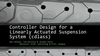
Controller Design for a Linearly Actuated Suspension System (cdlass). Dan Altman, Tim Reilley & Joseph Sholl Advisors: Prof. Gutschlag & Prof. Anakwa. Presentation Outline . Introduction of Team Members Project Summary Project Description Complete System Block Diagram

E N D
Controller Design for a Linearly Actuated Suspension System (cdlass) Dan Altman, Tim Reilley & Joseph Sholl Advisors: Prof. Gutschlag & Prof. Anakwa
Presentation Outline • Introduction of Team Members • Project Summary • Project Description • Complete System Block Diagram • Controller Flow Chart • Disturbance Using Cam Shaft • Hardware, Software, and Circuitry • Projected Schedule
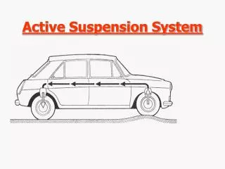
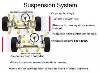
Project Summary We will design a controller for an electric linear actuator-based active suspension system. Initially, a position sensor will be used to determine the location of the “vehicle,” relative to the “wheel” position. The controller will use this information to engage the linear actuator to keep the mass at a relatively constant position. The addition of an accelerometer to the system will eventually be investigated to control the acceleration levels experienced throughout the range of available “wheel” displacement. LabVIEW will be used throughout the project as the controller platform. An additional deliverable of the project will be the creation of a tutorial (or guide) on the use of LabVIEW in controller design and implementation.
Current Project Goals • Model the system characteristics of the linear actuator • Implement National Instrument’s hardware and software (LabViewTM) to provide data acquisition and power electronics control • Create a tutorial for the use of National Instrument’s hardware and software (LabViewTM) • Implement a feedback position controller using National Instrument’s hardware and software (LabViewTM) to minimize the error • Reintegrate the linear actuator and H-bridge hardware into the suspension system due to the unavailability of the H-bridge hardware used previously
Project Description This project will involve focused efforts in power electronics design, system modeling and simulation, and feedback controller design. After the system and controller are simulated successfully utilizing Simulink, National Instrument hardware and software will be used to implement the feedback controller and provide control signals to the power electronics driving the active suspension system linear actuator.
Linear Actuator • Uses controller information from LabVIEW and potentiometer in order react to disturbances • Relationship between torque and applied force:
Linear Actuator/System Test • Based on the relationship between torque and applied force we derived the following equation to determine Tc and b:
Linear Actuator/System Test Trial 1: 8-2 ½ Lbs. Weights 20 Lbs or 9.07 kg Steady-State Approx. 20.5 V
Linear Actuator/System Test Trial 1: 10-2 ½ Lbs. Weights 25 Lbs or 11.34 kg Steady-State Approx. 49.2 V
Linear Actuator/System Test • Based on the previous group’s work, kE=0.382 [V/rad/sec] so • Trial 1: ω = 20.5 [V] / .382 [V/rad/sec] = 53.67 [rad/sec] • Trial 2: ω = 49.2 [V] / .382 [V/rad/sec] = 128.80 [rad/sec] • Using simultaneous equation solver: • Tc = 0.09304 b = 7.55 X 10⁻⁴
Disturbance Control • AC motor drives the cam • Variable Frequency Drive, Controls the speed of the AC motor • Single elliptical cam shape causes the disturbance while rotating
National Instrument Hardware •NI cDAQ-9174 NI CompactDAQ 4-slot USB 2.0 Chassis, 9 V - 30 V Input Voltage Range • NI 9211 4-Channel 24-Bit Thermocouple Input Module, 14 S/s sample rate, ± 80 mV • NI 9215 4-Channel 16-bit Analog Input Module, 100 kS/s/ch sample rate, ± 10 V • NI 9221 8-Channel 12-Bit Analog Input Module, 800 kS/s sample rate, ± 60 V
OriginalH-bridge and Gate Driver Hardware Fairchild FMG2G75US60 IGBT Power Module IR2110 Driver IR2110 We will utilize: • Two Fairchild Semiconductor FMG2G75US60 IGBT Power Modules • Two IR2110 High and Low Side Drivers • Four 6N137 High Speed 10MBit/s Logic Gate Optocouplers 6N137 Logic Gate Optocouplers
Revised H-bridge and Gate Driver Hardware HCPL 3120 • Gate Drive Optocoupler IRF640N Power MOSFET We will utilize: • Four (4) HCPL 3120 Gate Drive Optocouplers • Four (4) IRF640N MOSFETs • Reason for Change: • HCPL 3120 more robust, fewer chips, built-in optocoupling • IRF640N on hand
OriginalOptical Isolator Circuit (One Side of H-Bridge)
Revised H-Bridge Circuit with Bootstrap C1=C3=100µF=Cbs C2=C4=0.1µF 15 V 5 V 2*[2*Qg + Iqbs(max)/f + QLS + Icbs(leak)/f] 2*[2*20nC + 230µA/1 kHz + 5nC + 0/1 kHz] Cbs> ------------------------------------------------ *15 = ---------------------------------------------------------- *15 = 2µF [Vcc + Vf + VLS – Vmin] [15 V + 0.8 V + 0.3 V – 10 V]
Performance Specifications • The controller shall drive the linear actuator to maintain a midpoint level, yet to be determined, and minimize displacement for a disturbance with a frequency of 5 Hz • The system shall minimize displacement of the cab from the midpoint to ± ⅛” (3.175 mm) with no load • The system shall minimize displacement of the cab from the midpoint to ± ¼” (6.35 mm) with a load
Tutorial FIGURE 1 Step one: click on icon and drag to center. Screenshots and other figures Detailed step-by-step instructions
Division of Labor • Dan Altman – Control System Design / Web Page • Tim Reilley – Power Electronics / National Instruments Hardware Integration • Joseph Sholl – Labview Software Implementation / Tutorial Developer