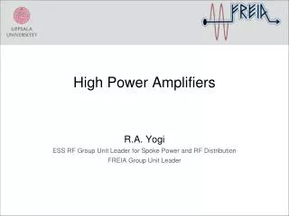
High Power A mplifiers
High Power A mplifiers. R.A. Yogi ESS RF Group Unit Leader for Spoke Power and RF Distribution FREIA Group Unit Leader . ESS: Superconducting 5 MW Linac. Frequency = 352.21 MHz Number of spoke resonators = 28 Maximum power to beam = 240 kW Maximum generator power = 300 kW .

High Power A mplifiers
E N D
Presentation Transcript
High Power Amplifiers R.A. Yogi ESS RF Group Unit Leader for Spoke Power and RF Distribution FREIA Group Unit Leader
ESS: Superconducting 5 MW Linac Frequency = 352.21 MHz Number of spoke resonators = 28 Maximum power to beam = 240 kW Maximum generator power = 300 kW
High Power Test Stand at Uppsala New design being developed at IPN Orsay High power testing needed ! Power Coupler Two high power RF chains are needed to test two spoke cavities at Uppsala test stand !
Baseline Design for ESS RF system • Generation and distribution of the RF power from a single source to a single accelerating cavity
Importance of selection of RF source The capital and running cost of an accelerator is strongly affected by the RF power amplifiers: Capital cost: • cost of the amplifiers • gain of the power amplifier (decides number of stages) and hence size and weight of the amplifiers: (decides gallery requirements) Running cost: • efficiency determines the electric power required and also amount of cooling needed • Life time: replacement, maintenance schedule
RF Source Requirements • Maximum RF power for a spoke resonator = 240 kW • Considering LLRF overhead = 15% (Simulink model shows 12.5% power overhead) • RF loss in distribution system = 5%,Power of RF source = 288 kW. Aim for 300 kW (4.0% extra, Why ? Will be explained in next slides) • Beam pulse width = 2.86 ms, repetition rate = 14 Hz, fill time of the cavity: Natural fill time = tf= 2QL / = 135 µs, (QL = 1.5 x 10⁶ )RF pulse width = 3.1 msDuty factor of the amplifier 4.28 % • Spoke cavity band-width = 2.34 kHz system band-width 100 times larger than spoke resonator band-width for tuning and regulation delay. 3dB bandwidth ≥ 250 kHz.
High Power RF Amplifier Specifications of RF Amplifier: Frequency = 352.21 MHz Power = 300 kW 3dB band-width ≥ 250 kW Pulse width = 3.1 ms Pulse repetition rate = 14 Hz No RF source exists at ESS specifications ! Hence development and prototyping is important ! Compared all the possible RF sources like Tetrode, Klystron, IOT, Solid state amplifier and selected Tetrode for the first high power RF chain. Simultaneously high power RF amplifier using solid state technology under development for the second chain. Supported by AIR and TB at ESS
Comparison of Tetrodes TH781, TH391 and TH595 tetrodes can be used at ESS specifications. TH595 is selected for first high power RF chain. Output power of two tetrodes needs to be combined.
Foot area:0.6m x 0.6m Foot area:2.5m x 2.5m
Schematic for first RF chain Loss in the connections are not considered due to the 4% margin on the generator power. SG: Signal generator, : Phase shifter, A: Attenuator, A1 & A2: Preamplifiers, PA1 & PA2: High power amplifiers. Transmitted power and RF distribution systems are specified on top of schematic.
Tetrode TH595 and cavity Th18595 A at Thales Amplifier cavity TH 18595A Tetrode TH595
Conclusion for High power RF Amplifier Comparison of target ESS specifications and achieved performance of TH595 and cavity Thus TH595 shall be used for first high power amplifier chain.
Pre-amplifier • As gain of tetrode decreases due to aging, conservative gain of 13 dB is considered while calculating specifications of solid state amplifier. • Thus output power of pre-driver = 8.7 kW. Aim for 10 kW. • Specifications of Predriver: • Frequency = 352.21 MHz • Output power = 10 kW • Gain = 70 dB • Total efficiency = 55 % • Class of operation: AB
Selected solid state amplifier after comparing the available technologies. • Gain 70 dB • Efficiency > 50 - 55% (class AB) • Good reliability: Built in redundancy • Modular system, easy replacement possible • Off-shelf available system RF unit of 700W power RF 5 kW power module
Conclusion • TH595 with amplifier cavity TH18595A can be used as high power amplifier • Solid state amplifier can be used as pre-driver. Thank you ! Comments and suggestions are welcome
10 kW 352MHz Pre-amplifier • Solid state amplifier: • Gain 73 dB, so only one stage • Good Reliability: Built in redundancy • Efficiency > 50 - 55% (class AB) • Modular system, so easy replacement possible • Triode: • Low Gain 10 dB, so consists of three amplifier stages. It requires pre-predriver triode (1 kW), and solid state low power amplifier (10 W) • Complex system. 3 amplifier stages, their power supplies, protections, hence low reliability. • Efficiency: 70%
Features RF Distribution • No pressurization • Use of Ferrite loads • Distribution at 3 levels • Half height WR2300: 350kW • 6-1/8 inch, 50 coax: 175 kW • 7/8 inch, 50 coax: 10 kW
Typical power sources used at 352 MHz are tetrodes, klystrons, IOTs and solid state amplifiers • Criteria of comparison: • Power distribution scheme • Lifetime • Efficiency • Gain • Availability • Costs
Klystron • Too big for 350 kW power • Size: 1 m x 1 m, weight: few tons • Efficiency: 60 – 65% • Modulator needed for power-supply,100 kV • Gain: 37 dB • Predriver not needed • Life time: 40-50 khours • Circulator needed for handling reflection • Base line of one RF amplifier per cavity
Solid state amplifier • 70 modules of 5 kW each that are combined • High reliability due to use of circulators and hybrid couplers. • Size: very big 10 m2 • Efficiency: 65% • Few distributed power supply 50 V, 200 A (low voltage, high current) • Gain: 37 dB • Predriver not needed • Life time: 50 khours RF unit of 700W power RF 5kW power module