Download
1 / 12
120 likes | 223 Vues
Explore a comprehensive FEA model database to analyze structure weight distribution, evaluate coil loadings, assess optimum support locations, and extract design data. Includes loads, constraints, material properties, and modeling assumptions.

E N D
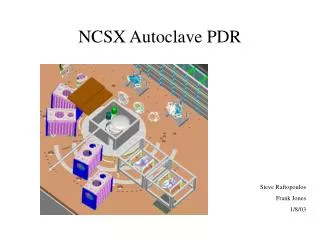
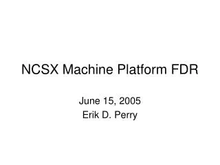
Descriptions of the NCSX Integrated Model – File6.db H. M. Fan, PPPL July 18, 2006
Objectives of the Model • Achieve more accurate structure weight distribution. • Include TF and PF coils loadings in the analysis. • Evaluate the TF structure influence on MCWF Joints • Provide a basic model for further modification of the modeling assumptions. • Run other EM load cases to verify present case (2T) is worse case. • Obtain interface loadings for bolt joints analysis. • Assess the optimum base support locations. • Extract useful data for base support design.
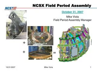
FEA model database consists of the following NCSX components in one field period (120 degrees): 1) Modular coils 2) MC winding form (MCWF) 3) MCWF poloidal breaks 4) MCWF toroidal shims 5) MCWF wing bag shims 6) PF coils No.4 to No.6 7) PF coil brackets and shims 8) TF coils 9) TF coil shims at inboard, outboard, top and bottom 10) TF inboard wedge spacers 11) Inboard TF structure 12) Outboard TF structure 13) Tie bars for (11) and (12) 14) TF structure toroidal shims 15) Connecting blocks between TF structure and MCWF 16) Fictitious base support blocks FEA Model
The Model database includes the following loads and displacement constraints: 1) EM loads based on 2T high beta current scenario at 0.0 seconds. 2) Coupled nodes on the two side faces of the MCWF. 3) Coupled nodes on the two end faces of PF coils. 4) Constraint equations for a cyclic symmetry TF structure. 5) Constraint equations for a cyclic symmetry TF wedge shims. 6) Displacement restraints Uy and Uz at one node in the base support block. Couples (green) and constraint equations (pink)
Applied Loads for the Structure Analysis • Dead loads: • The weight of model can be generated by acceleration in the solution stage. • One third of the center stack weight can be added in the solution stage. • Weight of vacuum vessel can be added in the solution stage. • EM loads: • EM loads are based on 2T high beta current scenario at 0.0 seconds. • EM forces are calculated on the basis of the total magnetic flux density. • The forces in the center stack are neglected due to self-balance. • Cool-down: • The relative thermal strain between the modular coil and the winding form is about 0.04% when they are cooled to 85K. • An equivalent temperature drop of 23.26K that produces corresponding coil strain of 0.04% was applied to the modular coils. • The temperatures on other parts are unchanged. • Four load cases: • Dead loads only at room temperature. • Dead loads plus cool-down to 85K • Dead loads, cool-down and EM at 85K • Dead loads and EM - Thermal strain during pulse assumed to cancel cool-down strain.
Material properties used in the Model: • Notes on shear modulus of elasticity: • Shear modulus are calculated from the isotropic material relationship except noted. • The 1st value is for Gxy and the 2nd value is for Gyz and Gxz.
Assumptionsand Modeling of Integrated Model: • Contact elements are mostly Linear except for the wing Interfaces. • The wing bag shims are bond to shells on one side and have frictionless unilateral contact behavior on the other side to the adjacent shell. • For the modular coil, the axial direction of the element coordinate system is z-axis. As modular coils are bonded to the tees, the smaller shear modulus of elasticity in Gyz and Gxz will lower the shearing stress at the interfaces and reduce the combined rigidity due to the composite action. • The shear rigidities of shims for the TF and PF coils are decreased for the intention of minimize the resistance to the coil movements. • In order to run on existing 32 bit PC with1.5GB total physical memory (936 MB available physical memory), the element size is not fine. The model has 163,090 elements and 283,750 nodes. • Fictitious base supports were added beneath the integrated model to simulate fundamental requirements of the permanent machine supports (Ref. 1). The model is supported on one nodal support that has vertical and toroidal restraints. • The weight of center stack in one field period were supported at the upper TF structure for conservative reason.
The following items do not included in the model: • To minimize the size of the model, the model disregarded the parts that have few contribution to the stiffness of the integrated system, such as vacuum vessel and center stack. However, the load impact from those part should be added in the solution phase. • To simplified the mesh pattern, the Pro/E geometry of the parts were modified to eliminate all bolt components and bolt holes at joints, and all fillets and chamfers at the right-angled edges or corners. • As the model did not consist of the modular coil clamp assembly, the modular coils were bonded to the winding forms. • The impacts of trim coils are not included. • No bolt preloads are considered in the analysis.
Solution Processor Inputs • Equation solver – No memory problems for both direct equation solver “SPARSE” and iterative equation solver “PCG” to be run in the PC with 32 bits and 1.5GB memory. • PCG requires less disk space. The default memory setting is OK. • SPARSE needs more disk space. To avoid the error of “ lack of memory”, it is better to set the maximum workspace memory with small database memory. In the runs, the memory was set to 1296 MB for the total workspace and 104 MB for the database. • The run time for the SPARSE solver may be faster if enough memory is provided for the workspace and database. • Convergence value – The displacement criterion was used for the convergence. As the EM loads is more difficult to converge due to coarse elements, separate tolerance values are selected depending on the load cases. • Without EM load, use default tolerance value of 0.05 • With EM load, use a tolerance value of 0.105
Loads Inputs at the Solution Phase • The dead loads are input as follow: • Use “ACEL,,,9.806” to specify the vertical acceleration for the model • Add one third of center stack weight [Ref. 2] on the TF structure • Add one third of vacuum vessel weight [Ref.3] on the shell support locations at the material part ID 90. • Cool-down strain - relative thermal strain between the modular coil and the winding form is about 0.04% when they are cooled to 85K • Set the reference temperature for the thermal strain calculation “TREF” at 0° K. • Input the nodal body temperature -23.2558° K for all modular coil nodes. • The EM loads based on 2T high beta current scenario at 0.0 seconds are incorporated in the model. No additional inputs are required
Future Study • The FEA model can be used as a basic model for further modification of the modeling assumptions to assess the impacts. • Consider different modular coil and TF coil material properties. • Loosen up the TF coil bonding assumption. • Change MCWF inboard contact behavior to frictionless. • Modify TF structure rigidly coupled to MCWF. • Modify contact bonding behavior of the TF structure shims to better simulate the eccentricity of the bolt connection. • Test different base support locations. • Run additional load cases to verify present case (2T) is worse case. • Extract useful data for bolt joints and base support designs.
References: sources and file [1] B. Nelson, “Requirements for stellarator core support “, March 14, 2006 [2] Drawing No. SE132-001 “Centerstack Assembly PF Coils 1, 2, & 3”, [3] F. Dahlgren, Nastran FEA model “model21bbe2a.dat”