1 / 2

Comparative Analysis of Fields in Single and Array Plasmonic Coaxial Waveguides

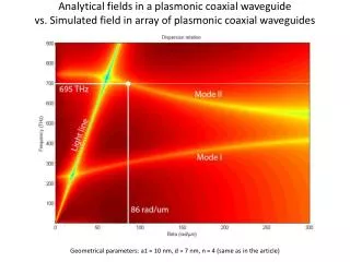
Explore the analytical and simulated fields in a plasmonic coaxial waveguide, comparing single and array configurations. Geometrical parameters include a1 = 10nm, d = 7nm, and n = 4. Animate the fields using a slideshow. Analytical and simulated data at f = 695 THz. Visualize the E-field components Ey, Ez, and power flow at 200nm incident plane wave.

Télécharger la présentation

Comparative Analysis of Fields in Single and Array Plasmonic Coaxial Waveguides

An Image/Link below is provided (as is) to download presentation Download Policy: Content on the Website is provided to you AS IS for your information and personal use and may not be sold / licensed / shared on other websites without getting consent from its author. Content is provided to you AS IS for your information and personal use only. Download presentation by click this link. While downloading, if for some reason you are not able to download a presentation, the publisher may have deleted the file from their server. During download, if you can't get a presentation, the file might be deleted by the publisher.

E N D

Presentation Transcript


  1. Analytical fields in a plasmonic coaxial waveguide vs. Simulated field in array of plasmonic coaxial waveguides Geometrical parameters: a1 = 10 nm, d = 7 nm, n = 4 (same as in the article)

  2. Animated fields: please use slideshow Analytical @ f = 695 THz (single coaxial plasmonic waveguide) Simulation @ f = 695 THz (unit cell of a waveguide array) y z x Ey E 200 nm Incident plane wave Power flow Ez

More Related