Download
1 / 29
300 likes | 478 Vues
Longitudinal Double Wing (LDW) /Second Generation/. Prepared by Michael & Faruk Dizdarevic For 10 th So. Cal. ASAT Conference. About Us. FARUK DIZDAREVIC (Principal Researcher) VP R&D Soko Aircraft Industry – the largest aircraft company in former Yugoslavia.

E N D
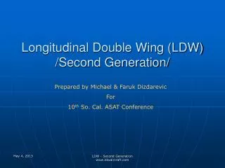
Longitudinal Double Wing (LDW) /Second Generation/ Prepared by Michael & Faruk Dizdarevic For 10th So. Cal. ASAT Conference LDW - Second Generation www.ldwaircraft.com
About Us FARUK DIZDAREVIC (Principal Researcher) • VP R&D Soko Aircraft Industry – the largest aircraft company in former Yugoslavia. • Previously a head of company’s Aircraft and Helicopter divisions involving manufacturing of their own military training and combat aircraft, as well as various components for World’s major aircraft including B737/757, MD-80, and A310/330/340, etc. • University professor for aircraft manufacturing technologies for many years. • Extensive experience and expertise related to the research of Flying Wing aerodynamic concepts for the past 20+ years. • Holder of a number of U.S. patents related to aeronautics field. LDW - Second Generation www.ldwaircraft.com
About Us …cont. MICHAEL DIZDAREVIC (Researcher ) • Research of Flying Wing aerodynamic concepts for the past 20+ years. • Versatile University level educational background in Mechanical and Aeronautical Engineering, as well as Finance and Computer Science. • Extensive work experience with large scale data processing, integration, modeling, and analysis with major US and international corporations including project management for the past 15 years. LDW - Second Generation www.ldwaircraft.com
Concept Overview • LDW is having a double wing configuration (Front and Rear Wing) as a hybrid between Tube-and-Wing (TAW) and Flying Wing aircraft. Front Wing is the main airlifting surface, while Rear Wing is an airlifting and main longitudinal stabilizing surface. • Elimination of virtually all parasitic surfaces, which are converted into airlifting surfaces while having similar handling characteristics to TAW aircraft. • One of the main contributing features of this architecture is the integration of engines with rear stabilizing and airlifting surfaces (Rear Wing) and their further integration with the Front Wing by a short V-tail. LDW - Second Generation www.ldwaircraft.com
Concept Overview …cont. • The rear position of engines is significantly reducing cabin and environmental noise, while thrust vectoring being used to additionally significantly improve pitch control at low flight speed. • Surface area increase of around 30% relative to comparable TAW aircraft still resulting with drastic aerodynamic efficiency improvement mainly due to increase of lifting to wetted area ratio from around 0.4 for TAW to 0.8 for LDW aircraft. • Significant increase of composite materials’ application relative to TAW aircraft due to favorable shapes of all sections and mutual distribution of inertia and aerodynamic forces. LDW - Second Generation www.ldwaircraft.com
Concept Summary • Payload and Weight - Significant increase in payload capacity and empty weight reduction due to specific LDW configuration and broad application of composite materials. • Drag – Efficient aft-camber airfoils with low relative thickness across the entire aircraft span, as well as long chords and low lift coefficient resulting with much lower drag. • Speed - Ability to fly at higher cruising altitudes and higher speed due to low specific wing loading and low airfoil relative thickness. • Specific Fuel Consumption All of the above drastically reducing specific fuel consumption. • Safety - Natural Dynamic Stability (5%+ Static Margin) with good pitch, roll, and yaw controls satisfying all safety requirements for commercial aviation. LDW - Second Generation www.ldwaircraft.com
1st LDW Gen. Challengesand 2nd Gen. Response C1. The ability of Vertical Reinforcement that is connecting Front and Rear Wing to effectively take on aerodynamic and inertia loadings of Rear Wing. R1. Removal of Vertical Reinforcement and direct integration of V-tail with Front Wing to address structural issues. C2. Safe transfer of Rear Wing loadings by means of V-tail into the rear portion of Front Wing. R2. Increase in volume and chord length of V-tail to further address structural issues. C3. Long distance of engines aft of Front Wing, which is having an adverse impact on gravity center of empty aircraft and inertia momentum with respect to Front Wing. R3. Significant forward shift of engines to shift empty aircraft gravity center forward and reduce inertia loadings on the Front Wing, while compensating for the loss of arm for longitudinal stabilization of aircraft with the combination of arm increase of lateral sections of Rear Wing and the increase of their surface area with further planform simplification. C4. Roll Maneuver effectiveness of outer sections of Front Wing. R4. Increasing the chords of outer sections of Front Wing to improve roll control. 1st LDW Gen. 2nd LDW Gen. LDW - Second Generation www.ldwaircraft.com
1st LDW Gen. Challengesand 2nd Gen. Response…cont C5. Payload underutilization relative to overall aircraft lift capacity. R5. Increasing the chords of the central section of Front Wing to allow for additional payload accommodation in the central section of the Front Wing by increasing the sweepback angle of the leading edge of Front Wing. C6. Position of main landing gear for some conditions. R6. Shifting main landing gears in aft direction to address some situations, especially operating weight empty condition. C7. Mutual proximity of aircraft engines and potential impact in case of catastrophic engine failures. R7. Increasing the lateral mutual distance of engines to increase the margin of safety in case of engine failures, especially catastrophic ones. C8. Span-wise elliptical loading of the Front Wing. R8. The subsequent analysis showed that other factors such as lower lift coefficient has a much higher impact on reduction of induced drag. In fact, the lower induced drag coefficient as the result of lower lift coefficient has a higher positive impact on induced drag reduction than both span-wise elliptical loading and higher aspect ratio combined as it results with significantly lower induced, compression, and wave drag. 1st LDW Gen. 2nd LDW Gen. LDW - Second Generation www.ldwaircraft.com
LDW 200 Weight Estimation The weight of LDW 200 aircraft (216 passengers) was computed based on NASA’s BWB methodology for the following sections: • Cabin • Aft Section of Front Wing • Rear Wing The weight of V-tail was computed by using a custom method, while the weight of lateral sections and other non-airframe components were computed based on generally accepted methods for present day Tube-and-Wing aircraft. LDW - Second Generation www.ldwaircraft.com
Weight Summary Comparison(LDW 200 vs. B767-300ER) LDW - Second Generation www.ldwaircraft.com
Gravity Center Positioning LDW 200 B767-300ER LDW - Second Generation www.ldwaircraft.com
Gravity Center Control Gravity center control of LDW aircraft is accomplished by utilizing the following parameters: • Size and shape of Front Wing • Size and shape of Rear Wing • Relative distance between Front and Rear Wing • Optimal distribution of payload and fuel mass LDW - Second Generation www.ldwaircraft.com
Drag Comparative Analysis(LDW 200 vs. B767-300ER) Cruise Conditions: B767-300ER LDW 200 LDW - Second Generation www.ldwaircraft.com
Parasitic Drag (lift independent drag)(LDW 200 vs. B767-300ER) Parasitic Drag of LDW 200 is lower by 12.54% when compared to B767 despite larger surface area by about 30% mainly due to lower dynamic pressure of 25%. Other factors that helped maintain a better margin is lower friction coefficient and lower form factor of LDW 200 airfoils due to higher Reynolds number (longer chords, higher Mach number) and lower relative thickness. LDW - Second Generation www.ldwaircraft.com
Induced Drag(LDW 200 vs. B767-300ER) Induced Drag of LDW 200 measured at mid-cruise is lower by 45% due to more than twice lower lift coefficient and 25% lower dynamic pressure despite much larger surface area and lower aspect ratio. B767-300ER LDW 200 LDW - Second Generation www.ldwaircraft.com
Wave Drag(LDW 200 vs. B767-300ER) Assumption: Identical airfoil family with pertinent t/c and Cl. B767-300ER LDW 200 LDW - Second Generation www.ldwaircraft.com
Interference Drag(LDW 200 vs. B767-300ER) Interference Drag for B767 was based on statistical evidence for such type of aircraft, which is roughly 2.5% of the total drag. The same percentage was applied to LDW 200 aircraft even though the interference zones are fewer and less pronounced when compared to B767 aircraft. LDW - Second Generation www.ldwaircraft.com
Drag Summary LDW - Second Generation www.ldwaircraft.com
Specific Fuel Consumption Aircraft Specific Fuel Consumption (SFC) is defined as fuel consumption (directly proportional to drag) per payload unit carried over a given distance during certain time. The above computation assumes the same Engine Specific Fuel Consumption (SFC) in cruising conditions for both B767 and LDW 200 engines. Since LDW 200 flies at a higher cruising altitude above troposphere (13,000 vs. 10,400 m for B767), SFC for LDW 200 will be somewhat greater. The research points to a probable increase of a few percentage points, which will be made up by increased engine ram drag due to increased speed and conically shaped air intakes of LDW 200 with minimal increase of aircraft drag due to well defined air intakes of LDW 200. LDW - Second Generation www.ldwaircraft.com
Pitch Control Comparison Pitch momentum of LDW 200 is 3.5 times higher than the one of B767 but the area of the Front Wing is 2.35 times larger while M.G.C. of Front Wing of LDW 200 is 3 times longer. Since LDW is behaving similarly as TAW aircraft in this respect, one can calculate Horizontal Tail Volume Vh factor (0.3-0.6 for well behaved systems) Vh = Sh x Lh/(S x C), which is 0.44 for LDW 200 aircraft and can go up to 0.52 with additional minor design changes. This does not include additional pitch control effects generated by engine thrust vectoring. LDW 200 B767-300ER LDW - Second Generation www.ldwaircraft.com
Roll Control Comparison Roll momentum generated by ailerons of Front Wing and elevons of Rear Wing of LDW 200 is more than twice higher than the same of B767 aircraft. However, the surface area of Front Wing of LDW 200 is 2.35 times larger though M.G.C. of LDW 200 has a much shorter arm from symmetry plane when compared to B767, thus generating lower disturbing roll momentums. Therefore, the roll efficiency of LDW 200 and B767 is rather close. LDW 200 B767-300ER LDW - Second Generation www.ldwaircraft.com
Yaw Control Comparison LDW 200 has a much lower lateral aerodynamic reflection than B767, as well as multiple times shorter distance of lateral engines from symmetry plane when compared with B767. The analysis shows that V-tail of LDW 200 aircraft exerts a sufficient level of yaw control in flight including in case of engine failure of one of outboard engines. LDW - Second Generation www.ldwaircraft.com
Conclusion The comparative analysis between LDW 200 and B767-300ER aircraft shows that LDW concept is providing for the following benefits: • Similar efficient flight controls including longitudinal natural stability due to powerful Rear Wing stabilizing effect and pitch controls including thrust vectoring as the result of a specific engine integration. • Drastically decreased wave drag due to significantly lower relative thickness and drastically lower lift coefficient, thus promising a significant increase in cruising speed for large aircraft deeply into transonic range with a potential to go as high as Mach 0.95. • Significant increase in payload capacity for comparable classes of present day aircraft due to larger airlifting surface area. • Considerable external environmental and passenger cabin noise reduction due to a specific engine integration with airframe and far aft position of engines relative to the passenger cabin. LDW - Second Generation www.ldwaircraft.com
Conclusion…cont. • A very significant reduction in specific aircraft fuel consumption as one of the key performance indicators with consequently longer range for given payload is based on the following major factors: • LDW aircraft is having the ability to carry significantly more payload with equivalent outer dimensions (LDW 200 is carrying about 75% more payload relative to B767) due to much lower aerodynamic drag sensitivity to mass increase as the result of significantly higher airlifting area. • Use of rather thin and efficient custom aft-camber airfoils due to significantly longer chords and much lower lift coefficient (2.5 times lower for LDW 200 relative to B767 aircraft), hence together generating much lower drag (especially induced, compression, and wave drag). • Much longer chords of LDW 200 aircraft are increasing Reynolds number values and consequently together with increased cruising speed decreasing skin friction coefficient, thus having a favorable impact on reduction of skin friction drag, while the lower form factor due to lower relative thickness of airfoils is further reducing overall parasitic drag. LDW - Second Generation www.ldwaircraft.com
Conclusion…cont. • Ability to fly at higher cruising altitudes with a lower lift coefficient (25% higher cruising altitude of LDW 200 aircraft with dynamic pressure being lower by as much when compared to B767) based on significantly higher effective lifting area (75-80% of total wetted area being engaged in lift production relative to under 40% for TAW aircraft in general), hence further considerably reducing overall drag due to resulting significantly lower specific wing loading. • Ability to fly at a higher speed at such higher altitudes additionally decreasing specific fuel consumption with marginal increase in wave and other drag due to lower dynamic pressure, significantly longer chords and subsequent lower relative airfoil thickness, as well as a lower lift coefficient due to larger airlifting surface area. • Most of the airframe (>80%) being favorable for the application of light composite materials, which together with favorable mutual distribution of inertia and airlifting forces across the airframe of LDW aircraft is having a favorable outcome on airframe sizing and weight reduction (25% operating weight empty reduction of LDW 200 relative to B767 aircraft), whereby all of the above having a cumulative positive effect on considerable specific fuel consumption reduction (more than 60% for LDW 200 relative to B767 aircraft). LDW - Second Generation www.ldwaircraft.com
Conclusion…cont. The adverse impacts of LDW design include the following: • Increase in wetted area of around 30% when compared to TAW aircraft, hence resulting with additional weight and skin friction drag. However, that cost is more than offset by a more favorable distribution of aerodynamic and inertia loading, hence resulting with reduction of specific airframe weight, while considerable drag reduction is achieved by a combination of a different cruising flight profile and other drag related factors that were previously described. • Increase in engines’ specific fuel consumption due to cruising flight profile of LDW aircraft above troposphere level (a few percentage points increase for LDW 200 relative to B767 aircraft) is expected to be offset by increased engine efficiency due to specific conical shapes of engines’ air intakes, thus resulting with net positive impact of engines’ ram drag with insignificant increase of aircraft drag. LDW - Second Generation www.ldwaircraft.com
Referenced Material LDW - Second Generation www.ldwaircraft.com
Q & A LDW - Second Generation www.ldwaircraft.com