COMPUTER MEMORY DESIGN
As mentioned above, a typical memory hierarchy starts with a small, expensive, and relatively fast unit, called the cache, followed by a larger, less expensive, and relatively slow main memory unit. Cache and main memory are built using solid-state semiconductor material (typically CMOS transistors). It is customary to call the fast memory level the primary memory. The solid-state memory is followed by larger, less expensive, and far slower magnetic memories that consist typically of the (hard) disk and the tape. It is customary to call the disk the secondary memory, while the tape is conventionally called the tertiary memory. The objective behind designing a memory hierarchy is to have a memory system that performs as if it consists entirely of the fastest unit and whose cost is dominated by the cost of the slowest unit. www.thesisscientist.com

COMPUTER MEMORY DESIGN
E N D
Presentation Transcript
CHAPTER 2 COMPUTER MEMORY DESIGN It is interesting to observe that as early as 1946 it was recognized by Burks, Goldstine, and Von Neumann that a computer memory has to be organized in a hierarchy. In such a hierarchy, larger and slower memories are used to supplement smaller and faster ones. This observation has since then proven essential in constructing a computer memory. If we put aside the set of CPU registers (as the first level for storing and retrieving information inside the CPU, then a typical memory hierarchy starts with a small, expensive, and relatively fast unit, called the cache. The cache is followed in the hierarchy by a larger, less expensive, and relatively slow main memory unit. Cache and main memory are built using solid-state semiconductor material. They are followed in the hierarchy by far larger, less expensive, and much slower magnetic memories that consist typically of the (hard) disk and the tape. Our deliberation in this chapter starts by discussing the characteristics and factors influencing the success of a memory hierarchy of a computer. 2.1. BASIC CONCEPTS In this section, we introduce a number of fundamental concepts that relate to the memory hierarchy of a computer. 2.1.1. Memory Hierarchy As mentioned above, a typical memory hierarchy starts with a small, expensive, and relatively fast unit, called the cache, followed by a larger, less expensive, and relatively slow main memory unit. Cache and main memory are built using solid-state semiconductor material (typically CMOS transistors). It is customary to call the fast memory level the primary memory. The solid- state memory is followed by larger, less expensive, and far slower magnetic memories that consist typically of the (hard) disk and the tape. It is customary to call the disk the secondary memory, while the tape is conventionally called the tertiary memory. The objective behind designing a memory hierarchy is to have a memory system that performs as if it consists entirely of the fastest unit and whose cost is dominated by the cost of the slowest unit. Get more Https://WWW.ThesisScientist.com
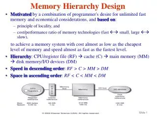
The memory hierarchy can be characterized by a number of parameters. Among these parameters are the access type, capacity, cycle time, latency, bandwidth, and cost. The term access refers to the action that physically takes place during a read or write operation. The capacity of a memory level is usually measured in bytes. The cycle time is defined as the time elapsed from the start of a read operation to the start of a subsequent read. The latency is defined as the time interval between the request for information and the access to the first bit of that information. The bandwidth provides a measure of the number of bits per second that can be accessed. The cost of a memory level is usually specified as dollars per megabytes. Figure 2.1 depicts a typical memory hierarchy. Table 6.1 provides typical values of the memory hierarchy parameters. The term random access refers to the fact that any access to any memory location takes the same fixed amount of time regardless of the actual memory location and/or the sequence of accesses that takes place. For example, if a write operation to memory location 100 takes 15 ns and if this operation is followed by a read operation to memory location 3000, then the latter operation will also take 15 ns. This is to be compared to sequential access in which if access to location 100 takes 500 ns, and if a consecutive access to location 101 takes 505 ns, then it is expected that an access to location 300 may take 1500 ns. This is because the memory has to cycle through locations 100 to 300, with each location requiring 5 ns. The effectiveness of a memory hierarchy depends on the principle of moving information into the fast memory infrequently and accessing it many times before replacing it with new information. This principle is possible due to a phenomenon called locality of reference; that is, within a given period of time, programs tend to reference a relatively confined area of memory repeatedly. There exist two forms of locality: spatial and temporal locality. Spatial locality refers to the Get more Https://WWW.ThesisScientist.com
CPU Registers Cache Latency Main Memory Bandwidth Secondary Storage (Disk) Speed Cost per bit T ertiaryStorage (T ape) Capacity (megabytes) Figure 6.1 Typical memory hierarchy TABLE 6.1 Memory Hierarchy Parameters Accesstype Capacity Latency Bandwidth Cost ƈ MB High CPU registers Random 64–1024bytes 1–10ns System clock rate 10–20MB 1–2MB Ljs 1–2MB ƈ s 1–2MB Ȉ s Cache memory Main memory Disk memory Tape memory Random Random Direct Sequential 8–512KB 16–512MB 1–20GB 1–20TB 15–20ns 30–50ns 10–30ms 30–10,000ms ƈ s $500 $20–50 $0.25 $0.025 phenomenon that when a given address has been referenced, it is most likely that addresses near it will be referenced within a short period of time, for example, consecutive instructions in a straightline program. Temporal locality, on the other hand, refers to the phenomenon that once a particular memory item has been referenced, it is most likely that it will be referenced next, for example, an instruction in a program loop. The sequence of events that takes place when the processor makes a request for an item is as follows. First, the item is sought in the first memory level of the memory hierarchy. The probability of finding the requested item in the first level is called the hit ratio, h1. The probability of not finding (missing) the requested item in the first level of the memory hierarchy is called the miss ratio, (12h1). When the requested item causes a “miss,” it is sought in the next subsequent memory level. The probability of finding the Get more Https://WWW.ThesisScientist.com
requested item in the second memory level, the hit ratio of the second level, is h2. The miss ratio of the second memory level is (1 _ h2). The process is repeated until the item is found. Upon finding the requested item, it is brought and sent to the processor. 2.2. CACHE MEMORY Cache memory owes its introduction to Wilkes back in 1965. At that time, Wilkes distinguished between two types of main memory: The conventional and the slave memory. In Wilkes terminology, a slave memory is a second level of unconventional high-speed memory, which nowadays corresponds to what i s called cache memory (the term cache means a safe place for hiding or storing things). CACHE MEMORY 109 (a small high-speed memory that is near the CPU). The end result is that at any given time some active portion of he main memory is duplicated in the cache. Therefore, when the processor makes a request for a memory reference, the request is first sought in the cache. If the request corresponds to an element that is currently residing in the cache, we call that a cache hit. On the other hand, if the request corresponds to an element that is not currently in the cache, we call that a cache miss. A cache hit ratio, hc, is defined as the probability of finding the requested element in the cache. A cache miss ratio (1 _ hc) is defined as the probability of not finding the requested element in the cache. In the case that the requested element is not found in the cache, then it has to be brought from a subsequent memory level in the memory hierarchy. Assuming that the element exists in the next memory level, that is, the main memory, then it has to be brought and placed in the cache. In expectation that the next requested element will be residing in the neighboring locality of the current requested element (spatial locality), then upon a cache miss what is actually brought to the main memory is a block of elements that contains the requested element. The advantage of transferring a block from the main memory to the cache will be most visible if it could be possible to transfer such a block using one main memory access time. Such a possibility could be achieved by increasing the rate at which information can be transferred between the main memory and the cache. One possible technique that is used to increase the bandwidth is memory interleaving. To achieve best results, we can assume that the block brought from the main memory to the cache, upon a cache miss, consists of elements that are stored in different memory modules, that Get more Https://WWW.ThesisScientist.com
is, whereby consecutive memory addresses are stored in successive memory modules. Figure 6.2 illustrates the simple case of a main memory consisting of eight memory modules. It is assumed in this case that the block consists of 8 bytes. Having introduced the basic idea leading to the use of a cache memory, we would like to assess the impact of temporal and spatial locality on the performance of the memory hierarchy. In order to make such an assessment, we will limit our deliberation to the simple case of a hierarchy consisting only of two levels, that is, the cache and the main memory. We assume that the main memory access time is tm and the cache access time is tc. We will measure the impact of locality in terms of the average access time, defined as the average time required to access an element (a word) requested by the processor in such a two-level hierarchy. M M M M M M M M 7 6 5 4 3 2 1 0 Byte Main memory Block Cache Figure 6.2 Memory interleaving using eight modules 2.2.1. Impact of Temporal Locality In this case, we assume that instructions in program loops, which are executed many times, for example, n times, once loaded into the cache, are used more than once before they are replaced by new instructions. The average access time, tav, is given by In deriving the above expression, it was assumed that the requested memory element has created a cache miss, thus leading to the transfer of a main memory block in time tm. Following that, n accesses were made to the same requested element, each taking tc. The above expression reveals that as the number of repeated accesses, n, increases, the average access time decreases, a desirable feature of the memory hierarchy. 2.2.2. Impact of Spatial Locality Get more Https://WWW.ThesisScientist.com
In this case, it is assumed that the size of the block transferred from the main memory to the cache, upon a cache miss, is m elements. We also assume that due to spatial locality, all m elements were requested, one at a time, by the processor. Based on these assumptions, the average access time, tav, is given by In deriving the above expression, it was assumed that the requested memory element has created a cache miss, thus leading to the transfer of a main memory block, consisting of m elements, in time tm. Following that, m accesses, each for one of the elements constituting the block, were made. The above expression reveals that as the number of elements in a block, m, increases, the average access time decreases, a desirable feature of the memory hierarchy. 2.2.3. Impact of Combined Temporal and Spatial Locality In this case, we assume that the element requested by the processor created a cache miss leading to the transfer of a block, consisting of m elements, to the cache (that take tm). Now, due to spatial locality, all m elements constituting a block were requested, one at a time, by the processor (requiring mtc). Following that, the originally requested element was accessed (n 2 1) times (temporal locality), that is, a total of n times access to that element. Based on these assumptions, the average access time, tav, is given by A further simplifying assumption to the above expression is to assume that tm ¼ mtc. In this case the above expression will simplify to. 2.2.4. Cache-Mapping Function Without loss of generality, we present cache-mapping function taking into consideration the interface between two successive levels in the memory hierarchy: primary level and secondary level. If the focus is on the interface between the cache and main memory, then the cache represents the primary level, while the main memory represents the secondary level. The same principles apply to the interface between any two memory levels in the hierarchy. In the following discussion, we focus our attention to the interface between the cache and the main memory. It should be noted that a request for accessing a memory element is made by the processor through issuing the address of the requested element. The address issued by the processor may correspond to that of an element that exists currently in the cache (cache hit); otherwise, it may correspond to an element that is currently residing in the main memory. Therefore, address translation has to be made in order to determine the whereabouts of the requested element. This Get more Https://WWW.ThesisScientist.com
is one of the functions performed by the memory management unit (MMU). A schematic of the address mapping function is shown in Figure 6.3. In this figure, the system address represents the address issued by the processor for the requested element. This address is used by an address translation function inside the MMU. If address translation reveals that the issued address corresponds to an element currently residing in the cache, then the element will be made available to the processor. If, on the other hand, the element is not currently in the cache, then it will be brought (as part of a block) from the main memory and placed in the cache and the element requested is made available to the processor. 113 6.2. CACHE MEMORY Secondary Level Memory Management Unit (MMU) Miss Translation Function Block Address in Primary Memory System Address Primary Level Hit Address mapping operation 2.2.5. Cache Memory Organization There are three main different organization techniques used for cache memory. The three techniques are discussed below. These techniques differ in two main aspects: 1. The criterion used to place, in the cache, an incoming block from the main memory. Get more Https://WWW.ThesisScientist.com
2. The criterion used to replace a cache block by an incoming block (on cache full). Direct MappingThis is the simplest among the three techniques. Its simplicity stems from the fact that it places an incoming main memory block into a specific fixed cache block location. The placement is done based on a fixed relation between the incoming block number, i, the cache block number, j, and the number of cache blocks, N: Example 1Consider, for example, the case of a main memory consisting of 4K blocks, a cache memory consisting of 128 blocks, and a block size of 16 words. Figure 6.4 shows the division of the main memory and the cache according to the direct-mapped cache technique. As the figure shows, there are a total of 32 main memory blocks that map to a given cache block. For example, main memory blocks 0, 128, 256, 384, . . . , 3968 map to cache block 0. We therefore call the direct-mapping technique many-to-one mapping technique. The main advantage of the direct-mapping technique is its simplicity in determining where to place an incoming main memory block in the cache. Its main disadvantage is the inefficient use of the cache. This is because according to this technique, a number of main memory blocks may compete for a given cache block even if there exist other empty cache blocks. This disadvantage should lead to achieving a low cache hit ratio. According to the direct-mapping technique the MMU interprets the address issued by the processor by dividing the address into three fields as shown in Figure 6.5. The lengths, in bits, of each of the fields in Figure 6.5 are: 1. Word field ¼ log2 B, where B is the size of the block in words. 2. Block field ¼ log2 N, where N is the size of the cache in blocks. 3. Tag field ¼ log2 (M/N), where M is the size of the main memory in blocks. 4. The number of bits in the main memory address ¼ log2 (B _ M) It should be noted that the total number of bits as computed by the first three equations should add up to the length of the main memory address. This can be used as a check for the correctness of your computation. Example 2 Compute the above four parameters for Example 1. Word field ¼ log2 B ¼ log2 16 ¼ log2 24 ¼ 4 bits Get more Https://WWW.ThesisScientist.com
Block field ¼ log2 N ¼ log2 128 ¼ log2 27 ¼ 7 bits Tag field ¼ log2(M/N) ¼ log2(22 _ 210/27) ¼ 5 bits The number of bits in the main memory address ¼ log2 (B _ M) ¼ log2 (24 _ 212) ¼ 16 bits. Having shown the division of the main memory address, we can now proceed to explain the rotocol used by the MMU to satisfy a request made by the processor for accessing a given element. We illustrate the protocol using the parameters given in the example presented above (Fig. 6.6). The steps of the protocol are: 1. Use the Block field to determine the cache block that should contain the element requested by the processor. The Block field is used directly to determine the cache block sought, hence the name of the technique: direct-mapping. 2. Check the corresponding Tag memory to see whether there is a match between its content and that of the Tag field. A match between the two indicates that the targeted cache block determined in step 1 is currently holding the main memory element requested by the processor, that is, a cache hit. 3. Among the elements contained in the cache block, the targeted element can be selected using the Word field. 4. If in step 2, no match is found, then this indicates a cache miss. Therefore, the required block has to be brought from the main memory, deposited in the cache, and the targeted element is made available to the processor. The cache Tag memory and the cache block memory have to be updated accordingly. Get more Https://WWW.ThesisScientist.com
Figure 6.6 Direct-mapped address translation The direct-mapping technique answers not only the placement of the incoming main memory block in the cache question, but it also answers the replacement question. Upon encountering a totally filled cache while a new main memory block has to be brought, the replacement is trivial and determined by the equation j ¼ i mod N. The main advantages of the direct-mapping technique is its simplicity measured in terms of the direct determination of the cache block; no search is needed. It is also simple in terms of the replacement mechanism. The main disadvantage of the technique is its expected poor utilization of the cache memory. This is represented in terms of the possibility of targeting a given cache block, which requires frequent replacement of blocks while the rest of the cache is not used. Consider, for example, the sequence of requests made by the processor for elements held in the main memory blocks 1, 33, 65, 97, 129, and 161. Consider also that the cache size is 32 blocks. It is clear that all the above blocks map to cache block number 1. Therefore, these blocks will Get more Https://WWW.ThesisScientist.com
compete for that same cache block despite the fact that the remaining 31 cache blocks are not used. The expected poor utilization of the cache by the direct mapping technique is mainly due to the restriction on the placement of the incoming main memory blocks in the cache (the many-to-one property). If such a restriction is relaxed, that is, if we make it possible for an incoming main memory block to be placed in any empty (available) cache block, then the resulting technique would be so flexible that efficient utilization of the cache would be possible. Such a flexible technique, called the Associative Mapping technique, is explained next. 3. VIRTUAL MEMORY . A virtual memory system attempts to optimize the use of the main memory (the higher speed portion) with the hard disk (the lower speed portion). In effect, virtual memory is a technique for using the secondary storage to extend the apparent limited size of the physical memory beyond its actual physical size. It is usually the case that the available physical memory space will not be enough to host all the parts of a given active program. Those parts of the program that are currently active are brought to the main memory while those parts that are not active will be stored on the magnetic disk. If the segment of the program containing the word requested by the processor is not in the main memory at the time of the request, then such segment will have to be brought from the disk to the main memory. The principles employed in the virtual memory design are the same as those employed in the cache memory. The most relevant principle is that of keeping active segments in the high-speed main memory and moving inactive segments back to the hard disk. Movement of data between the disk and the main memory takes the form of pages. A page is a collection of memory words, which can be moved from the disk to the MM when the processor requests accessing a word on that page. A typical size of a page in modern computers ranges from 2K to 16K bytes. A page fault occurs when the page containing the word required by the processor does not exist in the MM and has to be brought from the disk. The movement of pages of programs or data between the main memory and the disk is totally transparent to the application programmer. The operating system is responsible for such movement of data and programs. Get more Https://WWW.ThesisScientist.com
It is useful to mention at this point that although based on similar principles, a significant difference exists between cache and virtual memories. A cache miss can cause a time penalty that is 5 to 10 times as costly as a cache hit. A page fault, on the other hand can be 1000 times as costly as a page hit. It is therefore unreasonable to have the processor wait on a page fault while a page is being transferred to the main memory. This is because thousands of instructions could be executed on a modern processor during page transfer. The address issued by the processor in order to access a given word does not correspond to the physical memory space. Therefore, such address is called a virtual (logical) address. The memory management unit (MMU) is responsible for the translation of virtual addresses to their corresponding physical addresses. Three address translation techniques can be identified. These are direct-mapping, associative-mapping, and set- associative-mapping. In all these techniques, information about the main memory locations and the corresponding virtual pages are kept in a table called the page table. The page table is stored in the main memory. Other information kept in the page table includes a bit indicating the validity of a page, modification of a page, and the authority for accessing a page. The valid bit is set if the corresponding page is actually loaded into the main memory. Valid bits for all pages are reset when the computer is first powered on. The other control bit that is kept in the page table is the dirty bit. It is set if the corresponding page has been altered while residing in the main memory. If while residing in the main memory a given page has not been altered, then its dirty bit will be reset. This can help in deciding whether to write the contents of a page back into the disk (at the time of replacement) or just to override its contents with another page. In the following discussion, we will concentrate on the address translation techniques keeping in mind the use of the different control bits stored in the page table. 3.1. Direct Mapping Figure 7.9 illustrates the address translation process according to the direct-mapping technique. In this case, the virtual address issued by the processor is divided into two fields: the virtual page number and the offset fields. If the number of bits in the virtual page number field is N, then the number of entries in the page table will be 2N. Get more Https://WWW.ThesisScientist.com
The virtual page number field is used to directly address an entry in the page table. If the corresponding page is valid (as indicated by the valid bit), then the contents of the specified page table entry will correspond to the physical page address. The latter is then extracted and concatenated with the offset field in order to form the physical address of the word requested by the processor. If, on the other hand, the specified entry in the page table does not contain a valid physical page number, then this represents a page fault. In this case, the MMU will have to bring the corresponding page from the hard disk, load it into the main memory, and indicate the validity of the page. The translation process is then carried out as explained before. 144 MEMORY SYSTEM DESIGN II Figure 7.9 Direct-mapping virtual address translation The main advantage of the direct-mapping technique is its simplicity measured in terms of the direct addressing of the page table entries. Its main disadvantage is the expected large size of the page table. In order to overcome the need for a large page table, the associative-mapping technique, which is explained below, is used. 3.2.2. Associative Mapping Figure 7.10 illustrates the address translation according to the associative mapping technique. The technique is similar to direct mapping in that the virtual address issued by the processor is divided into two fields: the virtual page number and the offset fields. However, the page table used in associative mapping could be far shorter than its direct mapping counterpart. Every entry Get more Https://WWW.ThesisScientist.com
in the page table is divided into two parts: the virtual page number and the physical page number. A match is searched (associatively) between the virtual page number field of the address and the virtual page numbers stored in the page table. If a match is found, the corresponding physical page number stored in the page table is extracted and is concatenated with the offset field in order to generate the physical address of the word requested by the processor. If, on the other hand, a match could not be found, then this represents a page fault. In this case, the MMU will have to bring the corresponding page from the hard disk, load it into the main memory, and indicate the validity of the page. The translation process is then carried out as explained before. The main advantage of the associative-mapping technique is the expected shorter page table (compared to the direct-mapping technique) required for the translation process. Its main disadvantage is the search required for matching the virtual page number field and all virtual page numbers stored in the page table. Although such a search is done associatively, it requires the use of an added hardware overhead. Figure 7.10 Associative mapping address translation A possible compromise between the complexity of the associative mapping and the simplicity of the direct mapping is the set-associative mapping technique. This hybrid technique is explained below. Get more Https://WWW.ThesisScientist.com
3.2.3. Set-Associative Mapping Figure 7.11 illustrates the address translation according to the set-associative mapping. In this case, the virtual address issued by the processor is divided into three fields: the tag, the index, and the offset. The page table used in set-associative mapping is divided into sets, each consisting of a number of entries. Each entry in the page table consists of a tag and the corresponding physical page address. Similar to direct mapping, the index field is used to directly determine the set in which a search should be conducted. If the number of bits in the index field is S, then the number of sets in the page table should be 2S. Once the set is determined, then a search (similar to associative mapping) is conducted to match the tag field with all entries in that specific set. If a match is found, then the corresponding physical page address is extracted and concatenated with the offset field in order to generate the physical address of the word requested by the processor. If, on the other hand, a match could not be found, then this represents a page fault. In this case, the MMU will have to bring the corresponding page from the hard disk, load it into the main memory, update the corresponding set and indicate the validity of the page. The translation process is then carried out as explained before. Figure 7.11 Set-associative mapping address translation Get more Https://WWW.ThesisScientist.com
The set-associative-mapping technique strikes a compromise between the inefficiency of direct mapping, in terms of the size of the page table, and excessive hardware overhead of associative mapping. It also enjoys the best of the two techniques: the simplicity of the direct mapping and the efficiency of the associative mapping. It should be noted that in all the above address translation techniques extra main memory access is required for accessing the page table. This extra main memory access could potentially be saved if a copy of a small portion of the page table can be kept in the MMU. This portion consists of the page table entries that correspond to the most recent accessed pages. In this case, before any address translation is attempted, a search is conducted to find out whether the virtual page number (or the tag) in the virtual address field could be matched. This small portion is kept in the table look-aside buffer (TLB) cache in the MMU. This is explained below. 3.2.4. Translation Look-Aside Buffer (TLB) In most modern computer systems a copy of a small portion of the page table is kept on the processor chip. This portion consists of the page table entries that correspond to the most recently accessed pages. This small portion is kept in the translation look-aside buffer (TLB) cache. A search in the TLB precedes that in the page table. Therefore, the virtual page field is first checked against the entries of the Figure 7.11 Set-associative mapping address translation TLB in the hope that a match is found. A hit in the TLB will result in the generation of the physical address of the word requested by the processor, thus saving the extra main memory access required to access the page table. It should be noted that a miss on the TLB is not equivalent to a page fault. Figure 7.12 illustrates the use of the TLB in the virtual address translation process. The typical size of a TLB is in the range of 16 to 64 entries. With this small TLB size, a hit ratio of more than 90% is always possible. Owing to its limited size, the search in the TLB is done associatively, thus reducing the required search time. Get more Https://WWW.ThesisScientist.com
Figure 7.12 Use of the TLB in virtual address translation It should be noted that Intel’s Pentium 4 processor has a 36-bit address bus, which allows for a maximum main memory size of 64 GB. According to Intel’s specifications, the virtual memory is 64 TB (65,528 GB). This increases the processor’s memory access space from 236 to 246 bytes. This is to be compared to the PowerPC 604 which has two 12-entry, two-way set- associative translation look-aside buffers (TLBs): one for instructions and the other for data. The virtual memory space is therefore ¼ 252 ¼ 4 Peta-bytes. 3.2.5. Replacement Algorithms (Policies) Basic to the implementation of virtual memory is the concept of demand paging. This means that the operating system, and not the programmer, controls the swapping of pages in and out of main memory as they are required by the active processes. When a process needs a nonresident page, the operating system must decide which resident page is to be replaced by the requested page. The technique used in the virtual memory that makes this decision is called the replacement policy. Random ReplacementAccording to this replacement policy, a page is selected randomly for replacement. This is the simplest replacement mechanism. It can be implemented using a Get more Https://WWW.ThesisScientist.com
pseudo-random number generator that generates numbers that correspond to all possible page frames. At the time of replacement, the random number generated will indicate the page frame that must be replaced. Although simple, this technique may not result in efficient use of the main memory, that is, a low hit ratio h. Random replacement has been used in the Intel i860 family of RISC processor. First-In-First-Out (FIFO) ReplacementAccording to this replacement policy, the page that was loaded before all the others in the main memory is selected for replacement. The basis for page replacement in this technique is the time spent by a given page residing in the main memory regardless of the pattern of usage of that page. This technique is also simple. However, it is expected to result in acceptable performance, measured in terms of the main memory hit ratio, if the page references made by the processor are in strict sequential order. To illustrate the use of the FIFO mechanism, we offer the following example. ExampleConsider the following reference string of pages made by a processor: 6, 7, 8, 9, 7, 8, 9, 10, 8, 9, 10. In particular, consider two cases: (a) the number of page frames allocated in the main memory is TWO and (b) the number of page frames allocated are THREE. 6 7 8 9 7 8 9 10 8 9 10 8 8 7 7 9 9 8 8 10 6 6 7 7 9 9 8 7 10 10 9 9 a) 6 7 8 9 7 8 9 10 8 9 10 6 6 6 9 9 9 9 9 9 9 9 7 7 7 7 7 7 10 10 10 10 8 8 8 8 8 8 8 8 8 (b) faults was reduced to five. Since five pages are referenced, this is the optimum condition. The FIFO policy results in the best (minimum) page faults when the reference string is in strict order of increasing page number references. Least Recently Used (LRU) Replacement According to this technique, page replacement is based on the pattern of usage of a given page residing in the main memory regardless of the Get more Https://WWW.ThesisScientist.com
time spent in the main memory. The page that has not been referenced for the longest time while residing in the main memory is selected for replacement. The LRU technique matches most programs’ characteristics and therefore is expected to result in the best possible performance in terms of the main memory hit ratio. It is, however, more involved compared to other techniques. To illustrate the use of the LRU mechanism, we offer the following example. ExampleConsider the following reference string of pages made by a processor: 4, 7, 5, 7, 6, 7, 10, 4, 8, 5, 8, 6, 8, 11, 4, 9, 5, 9, 6, 9, 12, 4, 7, 5, 7. Assume that the number of page frames allocated in the main memory is FOUR. Compute the number of page faults generated. The trace of the main memory contents is shown in Figure 7.14. Number of page faults = 17. In presenting the LRU, we have a particular implementation, called stack-based LRU. In this implementation, the most recently accessed page is now represented by Figure 7.14 LRU replacement technique the top page rectangle. The rectangles do not represent specific page frames as they did in the FIFO diagram. Thus, each reference generating a page fault is now on the top row. It should be noted that as more pages are allotted to the program the page references in each row do not change. Only the number of page faults changes. This will make the set of pages in memory for n page frames be a subset of the set of pages for n þ 1 page frames. In fact, the diagram could be considered a STACK data structure with the depth of the stack representing the number of page frames. If a page is not on the stack (i.e., is found at a depth greater than the number of page frames), then a page fault occurs. Get more Https://WWW.ThesisScientist.com
Example Consider the case of a two-dimensional 8_8 array A. The array is stored in row-major order. For THREE page frames, compute how many page faults are generated by the following array-initialization loop. Assume that an LRU replacement algorithm is used and that all frames are initially empty. Assume that the page size is 16. The arrangement of the array elements in the secondary storage is shown in Figure 7.15. The sequence of requests for the array elements in the first TWO external loop executions is as follows: From the above analysis, it is clear that there will be one PF in every external loop execution. This makes the total number of PFs be 8. It should be noted that if the array was stored column- major, then every internal loop execution would generate eight page faults, thus causing the total number of PFs to become 64. Clock Replacement AlgorithmThis is a modified FIFO algorithm. It takes into account both the time spent by a page residing in the main memory (similar to the FIFO) and the pattern of usage of the page (similar to the LRU). The technique is therefore sometimes called the First- In-Not-Used-First-Out (FINUFO). In keeping track of both the time and the usage, the technique uses a pointer to Get more Https://WWW.ThesisScientist.com
151 7.2. IRTUAL MEMORﷀ Figure 7.15 Arrangement of array elements in secondary storage and main memory built up Get more Https://WWW.ThesisScientist.com
indicate where to place the incoming page and a used bit to indicate the usage of a given page. The technique can be explained using the following three steps. 1. If the used bit ¼ 1, then reset bit, increment pointer and repeat. 2. If the used bit ¼ 0, then replace corresponding page and increment pointer. 3. The used bit is SET if the page is referenced after the initial loading. 3.2.6. Virtual Memory Systems with Cache Memory A typical computer system will contain a cache, a virtual memory, and a TLB. When a virtual address is received from the processor, a number of different scenarios can occur, each dependent on the availability of the requested item in the cache, the main memory, or the secondary storage. Figure 7.17 shows a general flow diagram for the different scenarios. The first level of address translation checks for a match between the received virtual address and the virtual addresses stored in the TLB. If a match occurs (TLB hit) then the corresponding physical address is obtained. This physical address can then be used to access the cache. If a match occurs (cache hit) then the element requested by the processor can be sent from the cache to the processor. If, on the other hand, a cache miss occurs, then the block containing the targeted element is copied from the main memory into the cache (as discussed before) and the requested element is sent to the processor. The above scenario assumes a TLB hit. If a TLB miss occurs, then the page table (PT) is searched for the existence of the page containing the targeted element in the main memory. If a PT hit occurs, then the corresponding physical address is generated (as discussed before) and a search is conducted for the block containing the requested element (as discussed above). This will require updating the TLB. If on the other hand a PT miss takes place (indicating a page fault), then the page containing the targeted element is copied from the disk into the main memory, a block is copied into the cache, and the element is sent to the processor. This last Get more Https://WWW.ThesisScientist.com
Figure 7.16 FINUFO replacement technique Figure 7.17 Memory hierarchy accesses scenarios scenario will require updating the page table, the main memory, and the cache. A subsequent request of that virtual address by the processor will result in updating the TLB. 3.2.7. Segmentation A segment is a block of contiguous locations of varying size. Segments are used by the operating system (OS) to relocate complete programs in the main and the disk memory. Segments can be shared between programs. They provide means for protection from unauthorized access and/or Get more Https://WWW.ThesisScientist.com
execution. It is not possible to enter segments from other segments unless the access has been specifically allowed. Data segments and code segments are separated. It should also not be possible to alter information in the code segment while fetching an instruction nor should it be possible to execute data in a data segment. 3.2.8. Segment Address Translation In order to support segmentation, the address issued by the processor should consist of a segment number (base) and a displacement (or an offset) within the segment. Address translation is performed directly via a segment table. The starting address of the targeted segment is obtained by adding the segment number to the contents of the segment table pointer. One important content of the segment table is the Segment Number Offset Segment Table Displacement Physical Segment Base Address Physical Address Figure 7.18 Segment address translation physical segment base address. Adding the latter to the offset yields the required physical address. Figure 7.18 illustrates the segment address translation process. Possible additional information included in the segment table includes: 1. Segment length 2. Memory protection (read-only, execute-only, system-only, and so on) Get more Https://WWW.ThesisScientist.com
3. Replacement algorithm (similar to those used in the paged systems) 4. Placement algorithm (finding a suitable place in the main memory to hold the incoming segment). Examples include (a) First fit (b) Best fit (c) Worst fit 3.2.9. Paged Segmentation Both segmentation and paging are combined in most systems. Each segment is divided into a number of equal sized pages. The basic unit of transfer of data between the main memory and the disk is the page, that is, at any given time, the main memory may consist of pages from various segments. In this case, the virtual address is divided into a segment number, a page number, and displacement within the page. Address translation is the same as explained above except that the physical segment base address obtained from the segment table is now added to the virtual page number in order to obtain the appropriate entry in the page table. The output of the page table is the page physical address, which when concatenated with the word field of the virtual address results in the physical address. Figure 7.19 illustrates the paged segmentation address translation. Get more Https://WWW.ThesisScientist.com
Segment Number Virtual Page Number Offset Segment T able Displacement Physical Segment Base Address Page T able Physical Address Physical Address Figure 7.19 Paged segmentation address translation Get more Https://WWW.ThesisScientist.com