Download

1 / 23
230 likes | 309 Vues
Insight into recent progress and agreements on beam dynamics, machine layout, bunch compressor design, and main linac alignment from meetings at Snowmass. Expectations for the coming year and key decisions discussed.

E N D
Results from WG1 in Snowmass D. Schulte
Overview • Second ILC workshop at Snowmass to prepare the BCD • First meeting of GDE • Baseline configuration document to be ready end of the year • GDE meeting Frascati to discuss BCD • Next year costing of the design • BCD should contain baseline and proposed R&D • WG1 focused on beam dynamics • Conveners K. Kubo, P. Tenenbaum, D.S.
Organisation • First week ordinary workshop with presentations • Second week concentrated on discussions and recommendations • A list of decisions which need recommendations from T. Himmel • Preparation of workplan • Actual simulations
WG Goals at Snowmass • Agreement on beam parameters with GG1 • Bunch compressor design • Main linac configuration • Agreement on model assumptions • Agreement on necessary data standards • Agreement on plan for coming 16 months • Definition of tolerances and specifications • Beam dynamics simulations / benchmarking
Agreement on Beam Parameters with GG1 • Two main problems • Can a bunch compressor produce the short bunch length of 150um? • Yes • Can the luminosity target be met? • This is what we will try to answer in the coming year
Generic Machine Layout • We agreed on a generic beam line layout • Most lattices do not exist • But we greed on what the lattice should provide • Sub-systems are • DR to bunch compressor transport • Bunch compressors • Main linac • Beam delivery system (with WG4) • Spent beam line
DR to BC Transport • Matching region • Emittance measurement station • Necessary to separate the systems • Transverse collimation section • We are worried about halo from the damping ring • Feed-forward measurement • Feed-forward and turn-around were felt necessary to ensure beam stability, each bunch is kicked individually • Turn-around • Spin rotator • Feed-forward correction • Emittance diagnostics and skew correction section
Bunch Compressor • It was felt that a two stage bunch compressor is required • One stage performance for 6mm to 300um is marginal • 150um demands two-stage • Sufficient margin should be provided • Three designs were presented • A longer system by Peter Tenenbaum • A shorter system by Eun-San Kim • The longer was picked for BCD, since it is better investigated, will be revisited
Bunch Compressor Components • First RF section • First chicane • Collimators for longitudinal plane • Longitudinal diagnostics • Phase, length, correlations • Second RF section • Second chicane
Launch Region before Linac • Collimators for longitudinal plane • Longitudinal diagnostics • Transverse diagnostics • Transverse collimation/linac protection
Main Linac • Constant quadrupole spacing of about 24 cavities (GDE executive committee: 32) • 8 cavities per module from WG2 • Increase of spacing at higher energies should help but no agreement yet • One emittance measurement station • Different phase advance in both planes seems useful • Rotating wakefields can cause problems (R. Jones) • 60 degrees in x, 75 in y degrees
Beam Delivery System and Post Collision Line • Is designed by WG4 • Is an important ingredients in the integrated simulations • For luminosity estimates • E.g. banana effect • For understanding of diagnostics requirements • E.g. luminosity tuning
Tunnel Configuration • Three options • Laser straight • Following the earth curvature • Piece-wise straight • First can be more expensive • But safest from beam dynamics point of view • Simulations showed • The bends in piece-wise straight tunnel seem OK (P. Tenenbaum) • Following the earth curvature could be OK (N. Walker) • More detailed simulations confirm this (sofar) (A. Latina, K. Kubo, D.S.)
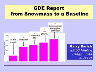
Models for Imperfection • A simple scattering model exists for prealignment • Based on ILC-TRC models • A model (LICAS, A. Reichold, G. Grzelak) for the survey line is interfaced to one code (PLACET) • Ground motion models exist (A. Seryi) • Vibration model not satisfactory • RF stability looks easier than for X-FEL • A central documentation would be useful
Bunch Compressor Alignment • Some sensitivity studies have been done by Peter Tenenbaum • Full alignment and tuning study to be done • Dynamic effects need study • Bunch compressor is essential for integrated simulations, since it couples longitudinal and transverse planes
Main Linac Alignment • Several simulations of dispersion free steering in main linac (J. Smith, K. Kubo, K. Ranjan, N. Solyak, D.S.) • Differences in the simulations made comparison difficult • Basic concept is variation of gradient • Results seem comparable • Main Linac emittance growth too large • Particularly difficult is first section where energy difference is small
Tuning Bump Performance • Tuning bumps can reduce emittance growth to acceptable level • See Peder Eliasson’s talk • Need dispersion tuning at the beginning and end of main linac • Measurement is done at the end • Wakefield bumps are also helpful • Felt need of one station in linac • In first part uncorrelated energy spread dominates • In second wakefields and correlated energy spread
Beam-Based Alignment of BDS • Very important area but not well covered • G. White showed first results of BPM to quadrupole alignment • Tuning studies shown in BDS working group • ATF2 will be perfect test bed
Feedback Simulations • Intra-pulse beam-beam feedback with realistic machine • This is a crucial ingredients ofthe ILC performance • Glen White showed encouraging results • More detailed understanding needed • Pulse-to-pulse feedback is not sufficient • Linda Hendrickson, Andrea Latina • Linda made a very detailed study • Energy jitter can confuse feedback in dispersion points in BDS
Interaction Point Tuning • Some useful signal exist • Incoherent pairs, Beamstrahlung, Radiative Bhabhas (but need to be careful) • Bhabhas at small angles are too slow • Tuning on the pairs (O. Napoly, D.S.) tested • Glen White used this signal for offset/angle optimisation • Tuning on proper combinations of beamstrahlung can work • Peder Eliasson, D.S. • Reconstruction of all beam parameters from beam signals seems very tough (G. White)
Integrated Simulations • Integrating all relevant sub-system into a simulation is required • Banana effect • Bunch compressor • Integration different timescales is important • E.g. ground motion during beam-based tuning • Cross talk of feedback systems
Code Development • Need to develop integrated simulation packages • Components exist but integration and extension is required • BC (BMAD, LIAR, Lucretia, SAD, MERLIN) • ML (BMAD, LIAR, Lucretia, SLEPT, PLACET, MERLIN) • BDS (BMAD, LIAR, Lucretia, SAD, PLACET, MERLIN) • IP (CAIN, GUINEAPIG) Benchmarking is vital • Want to have at least two codes for each area • Benchmarking with experiment (e.g. ATF2) • Agreed on lattice format • XSIF for now, XML later • Can we define better interface?
Conclusion • Quite a useful workshop • Had some time for discussion