Download
1 / 29
310 likes | 594 Vues
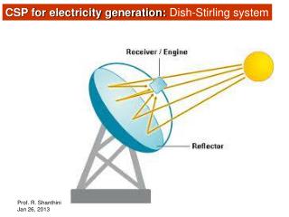
Stirling Engine System for Solar Thermal Generation and Energy Storage. LoCal Retreat, June 8-9 2009. Outline. Overview/Motivation System Description Early Prototypes Higher Power Engine Design. Thermal Energy Applications. Solar Thermal Dispatchable Generation

E N D
Stirling Engine System for Solar Thermal Generation and Energy Storage LoCal Retreat, June 8-9 2009
Outline • Overview/Motivation • System Description • Early Prototypes • Higher Power Engine Design
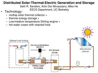
Thermal Energy Applications • Solar Thermal • Dispatchable Generation • Low cost, simple manufacturing • Thermal Storage • Dispatchable Resource • Low capital cost • Waste Heat Recovery • Free energy source – Industrial Processes, Combined Cycle • Low Temperature
Renewable Energy Challenges Renewable Energy Challenges Solar Thermal Advantages • Cost • Intermittency • Production bottlenecks • Lower Cost • Inherent Storage • Simple Manufacturing • Versatility
Intermittency and Energy Storage 1.5 MW Wind Turbine 4.6 MW Solar Installation Source: J. Apt, A. Curtright, “The Spectrum of Power from Utility-Scale Wind Farms and Solar Photovoltaic Arrays”, CEIC 2008
Cost Comparison Solar Thermal Photovoltaic Source: PV data from Solarbuzz
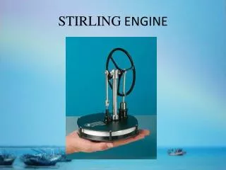
Stirling Engine • Can achieve large fraction (60-70%) of Carnot efficiency • Low cost, simple components • Fuel Flexible • Reversible • Scalable engine and storage capacity
Stirling Cycle Overview 4 1 2 3
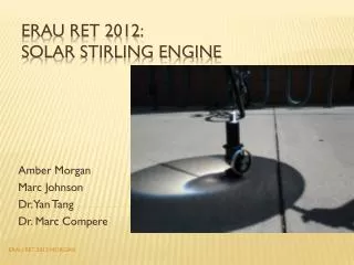
Research • Designed, built, tested two low power prototypes • Single phase and multiphase machines • Low power • Verified engineering models • Design of high power prototype • Improved simulation and design • Heat exchanger design • Optimization of geometry, parameters
Gamma-Type Free-Piston Stirling • Temperatures: Th=175 oC, Tk=25 oC • Working fluid: Air @ ambient pressure • Frequency: 3 Hz • Pistons • Stroke: 15 cm • Diameter: 10 cm • Indicated power: • Schmidt analysis 75 W (thermal input) - 25 W (mechanical output) • Adiabatic model 254 W (thermal input) - 24 W (mechanical output) Displacer Power piston
Reverser More Phases => Less Compression
Energy Flows and Losses Regenerator Ineffectiveness Heat Transfer Leakages Ideal Stirling Cycle Heat In Heater Cooler Rejected Heat Heater and ½ Regenerator Flow Loss Cooler and ½ Regenerator Flow Loss Internal Bearing & Motion Losses PV Work Out Alternator Inefficiency, Bearing Losses Gas Hysteresis Loss Electrical Output
Differences from prototypes • Design Improvements • Improved heat exchanger design • Refined simulation and models • Extensive optimization • Scaling • Increased pressure • Increased frequency • Increased volume • Relatively smaller losses
Efficiency and Power Output Contour Plot 20Hz, 25bar Air
What’s Next? • Finalize designs • Fabrication and testing of high power prototype • Design/experimental work with thermal storage • Explore waste heat electric generation • Economic analysis of cogen, energy storage opportunities
Residential Example • 30-50 sqm collector => 3-5 kWe peak at 10%eff • Reject 12-20 kW thermal power at peak. Much larger than normal residential hot water systems – would provide year round hot water, and perhaps space heating • Hot side thermal storage can use insulated (pressurized) hot water storage tank. Enables 24 hr electric generation on demand. • Another mode: heat engine is bilateral – can store energy when low cost electricity is available
Thermal Storage Example • Sealed, insulated water tank • Cycle between 150 C and 200 C • Thermal energy density of about 60 W-hr/kg, 60 W-hr/liter • Considering Carnot (~30%) and non-idealities in conversion (50-70% eff), remain with 10 W-hr/kg • Very high cycle capability • Cost is for container & insulator
Collector and Engine Efficiency G = 1000 W/m2 (PV standard) Schott ETC-16 collector Engine: 2/3 of Carnot eff.