Solar Stirling Engine Generator
Solar Stirling Engine Generator. Project Review Tara Dougherty Thomas Gamer Daniel Thering David Volzer. Overview:. Our Project Customer Needs What is a Beta Stirling Engine? System Architecture Design Features System Testing Results: Mechanical and Electrical

Solar Stirling Engine Generator
E N D
Presentation Transcript
Solar Stirling Engine Generator Project Review Tara Dougherty Thomas Gamer Daniel Thering David Volzer
Overview: • Our Project • Customer Needs • What is a Beta Stirling Engine? • System Architecture • Design Features • System Testing Results: Mechanical and Electrical • Objective Project Evaluation: Success and Failure • Opportunities and suggestions for improvement • Questions?
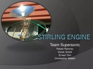
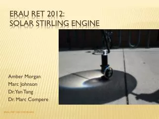
Our Project: • Design and construct a portable Stirling cycle engine generator that operates using solar energy.
Customer Needs: • The generator must produce 10 watts at 5 volts of electrical power • Must be weatherproof and operable for 1 year from the date it is set outside • Provide first generation design for further development of higher power applications • Must weigh less than 20 pounds • Total project budget not to exceed $500
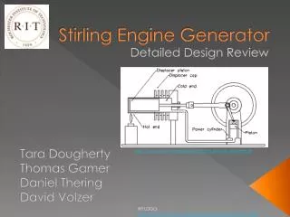
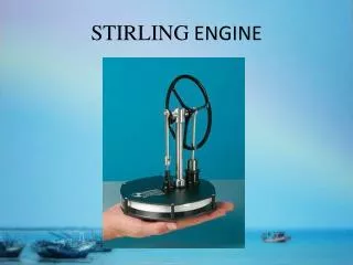
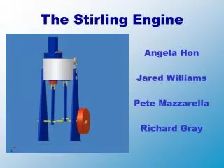
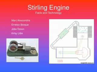
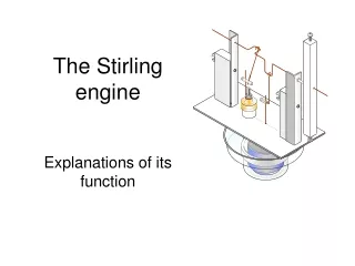
What is a Beta Stirling Engine? • Single power piston arranged coaxially with the displacer piston.
System Architecture • Dish Focuses Sunlight • Heat up copper cylinder • Pressurize chamber • Move power piston • Turn crankshaft • Turn pulleys • Generator turns • Charges Battery
Design Features • Machinable Ceramic Insulator • Brass nipple for pressurization • PTFE spring reinforced O-Rings • Turnbuckle linkages • PTFE impregnated bronze bushings/thrust washers • Stainless steel ball bearings • Power Rectification Circuit • Motor Controller • Lithium Polymer Charging Circuit
System Testing Results: Mechanical Heat Tape used as heat source. Note: At time 0, heat tape was at 70 % max power. At time 20, heat tape power was increased to 90 %. At time 35, heat tape power was increased to 99%. At time 55, fan was added to help cool heat sink Heat Tape used as heat source. Note: At time 0, heat tape was at 70 % max power. At time 20, heat tape power was increased to 90 %. At time 35, heat tape power was increased to 99%. At time 55, fan was added to help cool heat sink
Objective Project Evaluation: Success and Failure Failure: • Engine did not perform as expected due to: • Excessive friction • Possible lack of crankshaft momentum • Lack of counterweights on crankshaft prevented engine from sustaining motion. • Motor control board inoperative Success: • Mechanical: • Crankshaft can handle 300 RPM • Thermal: • Ceramic disc and heat sink functioned as designed • Electrical: • Power circuit had great overall efficiency and power output
Opportunities & Suggestions for Future Work • Improve seal technology • Improve compression ratio • Sun tracking system • Free standing base to support engine with 360 degree range of motion • Add counterweights to crankshaft • Larger Flywheel • High power testing • Re-evaluation of control logic • Seek outside sources for board fabrication