Download
1 / 16
180 likes | 402 Vues
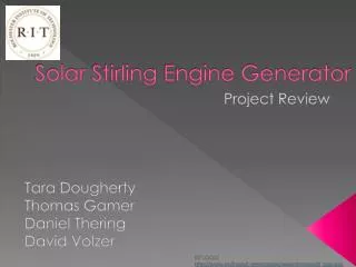
P12472 Solar Stirling Engine Generator: Final Presentation. Team P12472 Phil Glasser – Lead Engineer, Electrical Engineer William Tierney – Mechanical Engineer Bryan Abbott – Mechanical Engineer Mike Scionti – Mechanical Engineer

E N D
P12472 Solar Stirling Engine Generator: Final Presentation Team P12472 Phil Glasser – Lead Engineer, Electrical Engineer William Tierney – Mechanical Engineer Bryan Abbott – Mechanical Engineer Mike Scionti– Mechanical Engineer Dr. Alan Raisanen – Faculty Guide, Customer
Presentation Outline • Concept Summary • Customer Needs and Specs • System Architecture • Project Status • Schedule • Budget • System Testing Results • Major Issues, Future Work, and Suggestions • Objective Project Evaluation
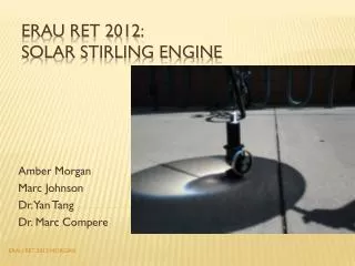
Project Description • We wish to demonstrate a small portable Stirling cycle electrical generator system that can be used to power small portable USB electronics. • Stirling generators can use any heat sourceto produce power including geothermal, waste heat and in our case solar energy. • Although mechanically more complex than photovoltaic systems, Stirling generator system efficiency can out perform photovoltaic system efficiency. • Our system will require the design of a solar collector component, a Stirling engine component, and an electrical generator, power conditioner and power storage component.
Customer Needs * Design meets custom all needs
Engineering Specifications • Power: Stirling generator must output at least 10 Watts of power when operating. • Voltage: Generator component must provide a nominal voltage of 5 Volts when operating. • Budget: Stirling generator assembly must be within the budget of $500. Approved for $517. • Weight: Stirling generator assembly must be within the weight requirement of 20 pounds. • Mean Time Between Failures: Stirling generator system must operate for one year before requiring maintenance. • Weatherproof: Stirling generator must be able to withstand all weather conditions.
Selected Concept • Selected concept was a single cylinder beta type Stirling engine with a 90 degree offset crankshaft to convert linear to rotational motion • This couples through pulleys and a timing belt to a PMDC motor which we used to both soft start the engine, and generate power through two buck-boost converters • Buck-boost circuits power USB devices, charge lead acid battery to power Arduino and soft start
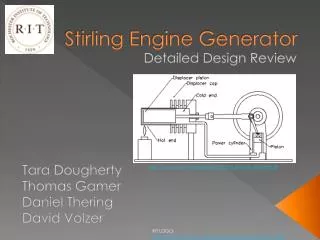
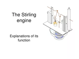
System Architecture Aluminum Solar Collector Chamber & Heat Sink Power & Displacer Piston Crankshaft Flywheel Belt and pulleys Thermocouples & MAX6675 PMOS FET PMDC Generator Power Conditioning USB Output Arduino Battery
Project Status • Electrical power generation, soft start, and battery charger all working and tested • Seals, Heat sink, solar collector, and separated piston and crankshaft/flywheel subassemblies • Possible Mechanical issues preventing engine from running • Crankshaft Misalignment • Friction in connecting rod bearings • Under-designed mounting brackets
Project Schedule • Machining took much longer than initially calculated • Rework on the crankshaft due to issues with construction • Redesign of mounting brackets • Base-plate redesign • Redesign of connecting rod – power piston, displacer piston connections • Fine-tuning of piston seals • Time was managed, engine was still built by week 8 but is currently not working due to mechanical issues
Budget • The project came in $20.43 over the approved budget of $517.09 • Over-budget due to under-estimated shipping costs
Electrical Testing Results • USB output begins when motor reaches ~1570 RPM. • Buck-boost can begin operating when generator voltage reaches 4.6V, and can operate in a boost mode down to 3.6V once powered on, and up to 18V (above the maximum voltage for this motor) • Custom electronics input and USB output shown at full load of 1.915A (9.745W), 5.05Vavg, 0.45Vp-p ripple within USB specification. • Successfully charged cell phones with power conditioning board
Mechanical Testing Results • Max differential 597 ºF at 1 hour, 450 ºF at 12 Minutes • Logarithmic heating curve, as expected • Temp Hot ~6X > Temp Cold • Heating tape used
Major Issues, Future Work, and Suggestions • Issue - Stirling engine does not run, possibly due to: • Crankshaft Misalignment • Friction in connecting rod bearings • Under-designed mounting brackets • Recommended Future Improvements: • Higher machining precision and sturdier design in mounting structure and crankshaft. • Higher precision in crankshaft - connecting rod – piston assembly.
Objective Project Evaluation • Overall, the electric portion of the project met all of the specs and customer needs. • The mechanical section ran into a couple snags with respect to friction and mechanical binding. • Built to our design, but unable to run. • For future iterations, we recommend a sturdier mounting structure and crankshaft and an overall stringent precision with respect to the crankshaft assembly.