The Stirling Engine
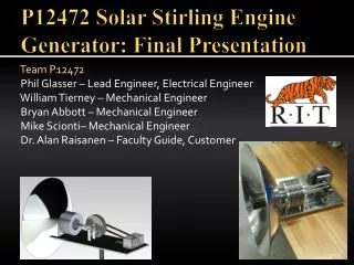
The Stirling Engine. Angela Hon Jared Williams Pete Mazzarella Richard Gray. ~History~. The Stirling Engine, originally known as the Economiser, was patented by Rev. Robert Stirling in Edinburgh, Scotland in 1816.

The Stirling Engine
E N D
Presentation Transcript
The Stirling Engine Angela Hon Jared Williams Pete Mazzarella Richard Gray
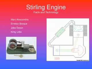
~History~ The Stirling Engine, originally known as the Economiser, was patented by Rev. Robert Stirling in Edinburgh, Scotland in 1816. The “Economiser” was originally developed as a safer alternative to steam engines; however, when steam engines were redesigned to be safer, Stirling engines became nearly obsolete. This simple engine can run on a variety of fuel sources, including flames, decaying vegetation, and even the heat of your hand. The Stirling Engine has a work output far closer to the theoretical ideal efficiency than most engines. Despite high efficiency and availability of fuel sources, the Stirling engine has always taken a back seat to more popular designs such as steam engines and internal combustion engines.
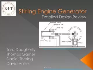
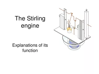
The Stirling Cycle COOLING: The left piston moves up while the right piston moves down. This pushes the hot gas into the cooled cylinder, which quickly cools the gas to the temperature of the cooling source, lowering its pressure. This makes it easier to compress the gas in the next part of the cycle. CONTRACTION: The piston in the cooled cylinder (right) starts to compress the gas. Heat generated by this compression is removed by the cooling source. EXPANSION: Heat is added to the gas inside the hot cylinder (left), causing pressure to build. Air expands, forcing the piston to move down. This is the part of the Stirling cycle that does the work. HEATING: The right piston moves up while the left piston moves down. This forces the gas into the heated cylinder, where it quickly heats up, building pressure, at which point the cycle repeats. Diagram taken from: http://electron9.phys. utk.edu/phys136d/modules/m3/m3ex1.htm
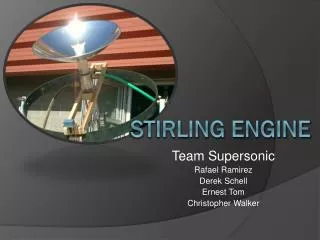
TSE-03 from http://www.bekkoame.ne.jp Our revised model Stirling Engine
OUR DESIGN CHANGES Changed design from metric to english, including bolts and holes Adjusted sizes of cylinders, pistons, heater, and holes in cylinder cover Redesigned pistons to make them solid and add o-ring groove. Changed materials for pistons and cylinders Added o-rings for sealing pistons into cylinders
Resources http://www.stirlingengine.com/ Link to the American Stirling Company, manufacturers of commercial and model Stirling Engines http://www.bekkoame.ne.jp/%7Ekhirata/english/mk_t03.htm Where we got our basic design http://travel.howstuffworks.com/stirling-engine.htm Howstuffworks- an excellent resource for understanding the Stirling Cycle http://web.vtc.edu/MEC/1012/Spr04_Group_Projects/Pirates/Web%20Pages/Group%20Webpage.html Our Web Site